Variant Bounded Region in Electrical Circuit
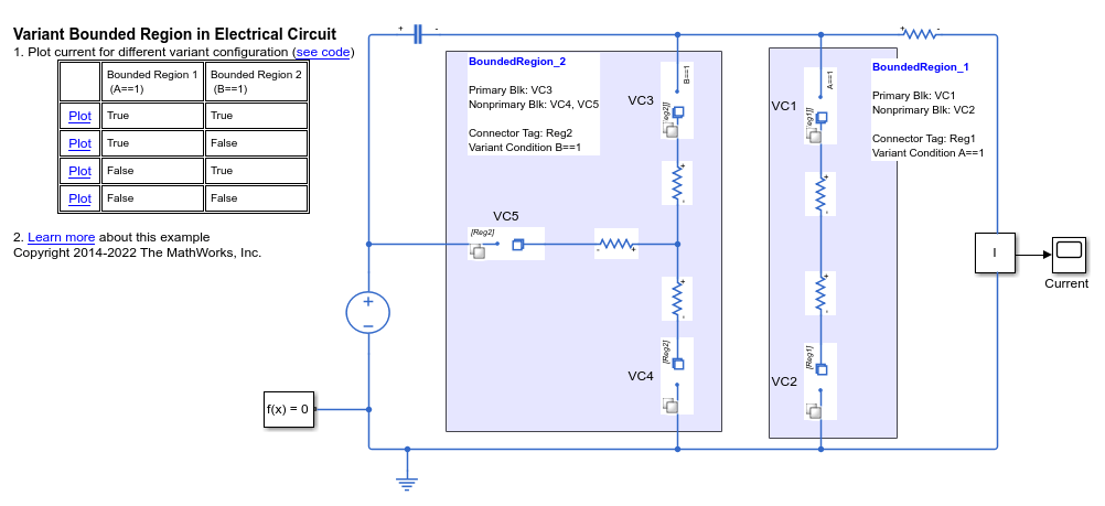
This example shows how to activate or deactivate the flow of a current to a set of components in an electrical circuit by using the primary and nonprimary type Variant Connector blocks. The primary and nonprimary Variant Connector blocks form a bounded region that allows you to vary the electrical circuit during simulation.
During simulation, Simulink® computes the variant conditions associated with each bounded region in the model. If the variant condition of a bounded region evaluates to true, all the physical components that are located inside the region become active. In this example, when A == 1 evaluates to true, the components of bounded region, BoundedRegion_1, become active and the components of BoundedRegion_2 remain inactive.
Model

Simulation Results from Simscape Logging
Case 1: BoundedRegion_1 Is Active and BoundedRegion_2 Is Inactive

Case 2: BoundedRegion_1 Is Inactive and BoundedRegion_2 Is Active
