Local Restriction (IL)
Restriction in flow area in isothermal liquid network

Libraries:
Simscape /
Foundation Library /
Isothermal Liquid /
Elements
Description
The Local Restriction (IL) block models the pressure drop due to a localized reduction in flow area, such as a valve or an orifice, in an isothermal liquid network.
Ports A and B represent the restriction inlet and outlet. The input physical signal at port AR specifies the restriction area. Alternatively, you can specify a fixed restriction area as a block parameter.
The block icon changes depending on the value of the Restriction type parameter.
| Restriction Type | Block Icon |
|---|---|
|
|
|
|

The restriction is adiabatic. It does not exchange heat with the environment.
The restriction consists of a contraction followed by a sudden expansion in flow area. The fluid accelerates during the contraction, causing the pressure to drop. In the expansion zone, if the Pressure recovery check box is cleared, the momentum of the accelerated fluid is lost. If the Pressure recovery check box is selected, the sudden expansion recovers some of the momentum and allows the pressure to rise slightly after the restriction.
Local Restriction Schematic
The block equations express the mass flow rate in terms of the pressure difference between ports A and B:
where:
Δp is the pressure differential.
pA and pB are pressures at ports A and B, respectively.
SR is the cross-sectional area at the restriction.
S is the cross-sectional area at ports A and B.
Δpcr is the critical pressure differential for the transition between the laminar and turbulent flow regimes.
Recr is the critical Reynolds number.
νatm is the liquid kinematic viscosity at atmospheric pressure, which is a global parameter defined by the Isothermal Liquid Properties (IL) block connected to the circuit.
Cd is the discharge coefficient.
is the average fluid mixture density.
ρA and ρB are fluid mixture density values at ports A and B, respectively. Equations used to compute the fluid mixture density depend on the selected isothermal liquid model. For detailed information, see Isothermal Liquid Modeling Options.
PRloss is the pressure loss ratio.
The pressure loss ratio, PRloss, depends on the Pressure recovery check box:
If pressure recovery is off, then
If pressure recovery is on, then
The cross-sectional area at the restriction, SR, depends on the Restriction type parameter value:
For variable restrictions,
where AR is the value of the input physical signal, and Smin and Smax are the values of the Minimum restriction area and Maximum restriction area block parameters, respectively.
For fixed restrictions, SR is the value of the Restriction area parameter.
By default, the block assumes that the cross-sectional area at the restriction ports is
much greater than the restriction area, setting the Cross-sectional area at ports A
and B parameter value to inf and all the
SR/S terms in the equations to
0, to improve computation efficiency. Specify an actual value for the
Cross-sectional area at ports A and B parameter if the two
cross-sectional areas are comparable in size and their ratio has an impact on flow
computations.
Examples
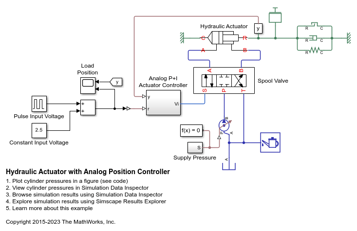
Hydraulic Actuator with Analog Position Controller
How the Foundation library can be used to model systems that span electrical, mechanical and isothermal liquid domains. In the model, a hydraulic system implemented in the isothermal liquid domain controls the mechanical load position in response to a voltage reference demand. If the reference demand is zero, then the hydraulic actuator (and load) displacement is zero, and if the reference is +5 volts, then the displacement is 100 mm.
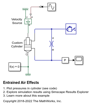
Entrained Air Effects
The effects of entrained air in a custom double acting cylinder. During the repeating cycle of oscillating pressure, the absolute pressure does not get below absolute zero as the bulk modulus of the homogeneous liquid-gas mixture decreases accordingly at low pressures.
Ports
Input
Conserving
Parameters
Extended Capabilities
Version History
Introduced in R2020a