Local Restriction (2P)
Restriction in flow area in two-phase fluid network

Libraries:
Simscape /
Foundation Library /
Two-Phase Fluid /
Elements
Description
The Local Restriction (2P) block models the pressure drop due to a localized reduction in flow area, such as a valve or an orifice, in a two-phase fluid network.
Ports A and B represent the restriction inlet and outlet. The input physical signal at port AR specifies the restriction area. Alternatively, you can specify a fixed restriction area as a block parameter.
The block icon changes depending on the value of the Restriction type parameter.
| Restriction Type | Block Icon |
|---|---|
|
|
|
|
The restriction is adiabatic. It does not exchange heat with the environment.
The restriction consists of a contraction followed by a sudden expansion in flow area.
Local Restriction Schematic
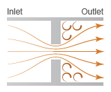
The fluid accelerates during the contraction, which causes the pressure to drop. After
passing through the restriction with some momentum loss, the fluid expands and decelerates
toward the outlet, allowing the pressure to rise slightly after the restriction. This pressure
loss model corresponds to the Control volume option of the
Pressure loss model parameter. It provides better accuracy but is less
robust and efficient than the default Bernoulli option, which
assumes uniform fluid density between the restriction inlet and outlet.
Use the Bernoulli option when:
The local restriction is operating in a fully subcooled liquid regime. The fluid is approximately incompressible and the uniform density assumption is appropriate.
The local restriction is used as an expansion valve in a refrigeration cycle. The fluid at the inlet is a subcooled liquid coming out of the condenser, therefore the uniform density assumption is appropriate.
The local restriction is operating in a fully superheated vapor regime, but the flow velocity is low subsonic, which is typically the case in HVAC systems. In this case, the density also does not change much and the uniform density assumption is appropriate.
For all other situations, you can also use the Bernoulli option
to trade accuracy for a faster and more robust simulation.
Mass Balance
The mass balance equation is
where:
and are the mass flow rates into the restriction through port A and port B.
Energy Balance
The energy balance equation is
where ϕA and ϕB are the energy flow rates into the restriction through port A and port B.
The local restriction is assumed to be adiabatic, and therefore, the change in specific total enthalpy is zero. At port A,
while at port B,
where:
uA, uB, and uR are the specific internal energies at port A, at port B, and the restriction aperture.
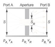
pA, pB, and pR are the pressures at port A, port B, and the restriction aperture.
νA, νB, and νR are the specific volumes at port A, port B, and the restriction aperture.
wA, wB, and wR are the ideal flow velocities at port A, port B, and the restriction aperture.
The block computes the ideal flow velocity as
at port A, as
at port B, and as
inside the restriction, where:
is the ideal mass flow rate through the restriction.
S is the flow area at port A and port B.
SR is the flow area of the restriction aperture.
The block computes the ideal mass flow rate through the restriction as:
where CD is the flow discharge coefficient for the local restriction.
Local Restriction Variables
Momentum Balance if Using Bernoulli Equation
The mass flow from port A to port B is:
where:
Δplam is the threshold pressure drop at which the flow begins to smoothly transition between laminar and turbulent.
vin is the inlet specific volume. Which port serves as the inlet and which serves as the outlet depends on the pressure differential across the restriction. If pressure is greater at port A than at port B, then port A is the inlet; if pressure is greater at port B, then port B is the inlet.
PRloss is the pressure loss ratio.
The pressure loss ratio, PRloss, is the ratio of the pressure difference between the inlet and the outlet to the pressure difference between the inlet and the restriction. It is a term that accounts for the pressure recovery during the flow expansion after the restriction:
Momentum Balance if Using Control Volume Analysis
The mass flow from port A to port B for turbulent flow is:
KT is defined as:
where the subscript in denotes the inlet port and the
subscript out the outlet port. Which port serves as the inlet and which
serves as the outlet depends on the pressure differential across the restriction. If
pressure is greater at port A than at port B, then
port A is the inlet; if pressure is greater at port
B, then port B is the inlet.
The mass flow rate from port A to port B for laminar flow is:
Δplam denotes the threshold pressure drop at which the flow begins to smoothly transition between laminar and turbulent:
where Blam is the Laminar flow pressure ratio parameter. The flow is laminar if the pressure drop from port A to port B is below the threshold value; otherwise, the flow is turbulent.
The pressure at the restriction area, pR, also depends on the flow regime. When the flow is turbulent:
When the flow is laminar:
Assumptions and Limitations
The restriction is adiabatic. It does not exchange heat with its surroundings.
The
Bernoullipressure loss model assumes uniform fluid density between the inlet and the outlet of the restriction.