Battery Single Particle

Libraries:
Simscape /
Battery /
Cells
Description
The Battery Single Particle block represents a battery by using a single-particle model. This implementation considers the ohmic and mass transport overpotentials in both the liquid electrolyte and solid electrode phases. Additionally, it considers the reaction kinetics and the current collector resistance.
The battery comprises two electrodes, the anode and cathode, and a porous separator between the electrodes. In this block, the anode refers to the negative electrode during discharge and the cathode refers to the positive electrode during discharge. The block models the ohmic overpotentials of the electrodes and electrolyte, as well as the concentration across the cell cross section from the anode current collector to the cathode current collector, in a one-dimensional framework.
This figure illustrates a representative concentration in the electrolyte during discharge. The model comprises the anode (x=[0 … L-]), the separator (x=[L- … L-+Lsep]) and the cathode (x=[L-+Lsep… L-+Lsep+L+]).

The block calculates the concentration in the electrodes in representative spherical particles across the radial dimension r. This figure shows the concentration gradient in the representative particles during a continuous discharge of the battery:

Species Conservation in Solid Phase
When the block is in solid phase, the single-particle approach models the positive and negative electrodes as a single representative spherical particle.
Note
The superscripts in these equations refer to the respective electrodes. A + superscript refers to the cathode. A - superscript refers to the anode. A sep superscript refers to the separator. A ± superscript means that the equation applies to both anode and cathode. For example, c+s is the solid-phase concentration of the cathode and c-s is the solid-phase concentration of the anode.
This equation uses Fick's law to describe the concentration, c, of the cation in the negative or positive electrode. The block uses the radial coordinates only to calculate the concentration in the electrodes. The diffusion in the spherical particle drives the mass transfer,
where:
cs is the solid-phase concentration.
Ds is the diffusion coefficient in solid phase.
r is the radius.
t is the time.
At the center of the particle, the concentration gradient is equal to 0:
This equation calculates the ion concentration gradient at the surface of the particle:
In this equation, F is Faraday's constant, and J is the molar flux,
where:
I is the current applied to the cell.
A is the total area of the current collector.
L is the length of the respective electrode.
Additionally, a is the active surface area per electrode unit volume,
where:
ε is the active material fraction of the electrode.
R is the total radius of the active particle.
To solve the differential equation, the Battery Single Particle block discretizes the particle with the radius R into n shells. Each shell has a radial distance equal to from the adjacent spheres.
For the ith sphere, this equation calculates the rate of change of concentration, δc/δt:
For the innermost shell in the particle, the block implements this boundary condition:
To implement the boundary condition at the surface of the particle, the block adds an additional node around the surface. The block does not calculate the concentration of this node because it does not physically exist. The block uses this node to calculate the boundary condition between the outermost shell in the particle and the non-existent shell around it by using the Neumann boundary condition. This equation describes the discretized result at the surface of the particle:
Mass Transport Overpotential in Solid Phase
When the block is in solid phase, the open-circuit potential depends on the concentration. To calculate the mass transport overpotential at the electrodes, the Battery Single Particle block subtracts the open-circuit potential of the average relative concentration in the particle from the open-circuit potential of the average relative concentration at the surface,
where:
ηdiffusion,s is the solid-phase mass transport overpotential.
ocp(cs,surface,relative) is the open-circuit potential for the concentration at the surface of the particle.
ocp(csrelative) is the open-circuit potential for the average concentration of the particle.
The block uses the same equation to calculate the mass transport overpotential for both the anode and the cathode.
Ohmic Overpotential in Solid Phase
To calculate the ohmic overpotential when the block is in the solid phase, the Battery Single Particle block linearly approximates the current across the electrodes and the current at the current collector to a value equal to the electric current applied to the cell. The current at the interface between the current separator and the electrode is zero. This equation defines the ohmic overpotential in the solid phase,
where:
ηohmic,s is the solid-phase ohmic overpotential.
Ibatt/A is the cell cross section.
L is the length of the respective electrode and depends on the thickness of the anode or cathode.
κ is the conductivity. The conductivity depends on the temperature of the cell. κ is equal to the Anode conductivity parameter when the block calculates the ohmic overpotential of the anode and is equal to the Cathode conductivity parameter when the block calculates the ohmic overpotential of the cathode.
The block uses the same equation to calculate the ohmic overpotential in solid phase for both the anode and the cathode.
Species Conservation in Liquid Phase
When the block is in liquid phase, this equation describes the concentration in the electrolyte at both electrodes and at the separator. To calculate the concentration across the separator, the block considers the diffusive flow induced by concentration gradient,
where:
cε is the concentration in the electrolyte.
Dε is the diffusion coefficient in liquid phase.
x is the location in the thickness of the battery, from the anode current collector to the cathode current collector.
t is the time.
At the positive and negative electrodes, the block considers both the diffusive flow and the cation flux from the solid electrode into the electrolyte,
where:
∈ is the volume fraction of the electrolyte.
Deffε is the diffusion coefficient in the liquid phase that considers the porosity of the material. The diffusivity of the liquid electrolyte depends on the properties of the surrounding solid electrode material. The electrode comprises multiple components, such as the active material and the filler, that form a characteristic porous material.
J is the molar flux.
t+ is the transference number of the cation.
F is Faraday's constant.
Because the electrolyte is a continuous fluid, the cation concentration at the border between the negative and positive electrodes and the separator must be equal. For the concentration in the electrolyte at the anode-separator and cathode-separator interfaces, the block must define the boundary conditions between the three sections of the battery. The block represents both electrodes and the separator as cuboids.
This block considers the electrolyte as a continuous medium across the electrodes and the separator. Because the concentrations on both sides of the interface must be equal, a continuity boundary condition exists for the interface between the electrodes and the separator.
This equation describes the continuity boundary condition for the concentration at the interface between the anode and the separator,
where:
is the concentration in the anode at the border between the anode and the separator.
is the concentration in the separator at the border between the anode and the separator.
This equation describes the continuity boundary condition for the concentration at the interface between separator and cathode,
where:
is the concentration in the separator at the border between the separator and the cathode.
is the concentration in the cathode at the border between the separator and the cathode.
The block also applies a flux boundary condition to the interfaces between the electrodes and the separator. The flux at both sides of the interface must be equal,
where:
is the diffusion coefficient of the anode.
is the diffusion coefficient of the cathode.
is the diffusion coefficient of the separator.
is the concentration gradient of the anode at the border between the anode and the separator.
is the concentration gradient of the separator at the border between the anode and the separator.
is the concentration gradient of the cathode at the border between the cathode and the separator.
is the concentration gradient of the separator at the border between the cathode and the separator.
This equation specifies the concentration at the boundaries between the electrodes and the current collectors. The flux is proportional to the flux at the current collector, which is equal to zero because the block does not store any ions there. Hence the resulting flux at the interface is zero,
where:
is the concentration gradient in the anode at the border between the anode and the leftmost current collector.
is the concentration gradient in the cathode at the border between the cathode and the rightmost current collector.
Similar to the solid phase, the block solves the differential equation by dividing the electrolyte into n sections of equal size. This equation expresses the concentration in the ith section with a distance δx between sections, and is valid for all [1,Ms-1] sections:
The block discretizes the separator using the equation:
To calculate the concentrations at the interfaces between the electrodes and the separator, the block applies all the boundary conditions. For example, for the interface between the anode and the separator, the block applies the equation:
Mass Transport Overpotential in Liquid Phase
When the block is in the liquid phase, it uses the concentrations at the interfaces between the current collector and the anode and at the interfaces between the cathode and the current collector to calculate the mass transport overpotential in the electrolyte using the equation,
where:
R is the universal gas constant.
T is the temperature.
F is Faraday's constant.
Ohmic Overpotential in Liquid Phase
When the block is in the liquid phase, it calculates the ohmic overpotential by linearly approximating the ionic current in each section of the battery. For the electrodes, the ionic current at the interface to the current collector is zero. At the interface to the separator, the ionic current is equal to the electric current of the battery, Ibatt. Across the separator, the block approximates the ionic current as constant and equal to the electric current applied to the battery. The block calculates the ohmic overpotential using the equation
where κeff is the effective conductivity that the block calculates by using the Bruggeman coefficient. For more information about effective parameters, see the Effective Electrolyte Properties section.
Charge Transfer Overpotential
To model the charge transfer overpotential, this block uses the Butler-Volmer equation. The Butler-Volmer equation describes the relationship between the current density, j, and the overpotential, η, which is the difference between the actual electrode potential and the thermodynamic equilibrium potential. The Butler-Volmer equation is
where:
α is the charge transfer coefficient for the oxidation and reduction.
i0 is the exchange current density.
Solving the equation for the electrode overpotential results in these equations:
i±0 is the exchange current density in the anode and in the cathode and is equal to
where:
k is the charge transfer rate constant and is equal to the value of the Charge transfer rate constant for Anode parameter for the anode and to the value of the Charge transfer rate constant for Cathode parameter for the cathode.
is the average electrolyte concentration.
cs,max is the maximum electrode concentration.
cs,surf is the electrode surface concentration.
To calculate the kinetic overpotential of the complete cell, the block subtracts the kinetic overpotential at the anode from the kinetic overpotential at the cathode:
Lithium Plating
Since R2026a
Lithium plating occurs when the lithium ions deposit on the anode surface as metallic lithium due to the diffusion limitations during charging. This process happens at high charge rates or at low temperatures, where the slow diffusion of the lithium ions prevents them from intercalating into the anode material.
Lithium plating leads to irreversible capacity loss and can cause safety issues, including short circuits and thermal runaway. It also contributes to loss of lithium inventory (LLI), as the plated lithium is no longer available for electrochemical reactions.
To model lithium plating in the Battery Single Particle block, set the Plating modeling
method parameter to Fractional reversible plating.
During the plating process, a fraction of the generated plated lithium is reversible and can
be stripped once the potential rises. The remaining plated lithium is irreversible and
cannot be stripped. You can specify the amount of reversible and irreversible plated
material by setting the value of the Amount of reversible plated
material and Amount of irreversible plated material public
variables in the Initial Targets section.
This figure shows a visual representation of the plating and stripping processes.
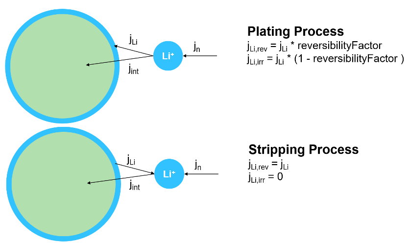
In this figure:
jn is the total current density.
jint is the current density of the intercalation reaction.
jLi is the current density of the lithium plating reaction.
jLi,rev and jLi,irr are the current density of the reversible and irreversible lithium plating, respectively.
reversibilityFactor is the fraction of the plating process that is reversible.
Under the assumption that the total current density jn is much greater than the current density of the lithium plating jLi, you can neglect the current density of the intercalation jInt that takes part in the reaction. The block then uses the total current density jn to directly calculate the charge transfer overpotential. To calculate the current density of the lithium plating, the block uses this extended Butler-Volmer equation,
where:
i0,Li is the exchange current density for the lithium plating reaction.
αa,Li is the anodic charge transfer coefficient and is equal to 0.5.
αc,Li is the cathodic charge transfer coefficient and is equal to 0.5.
ηLi is the overpotential of the lithium plating reaction.
R is the universal gas constant.
F is the Faraday's constant.
T is the temperature.
Since the block does not directly calculate the electrode and electrolyte potentials, this equation defines the plating overpotential ηLi:
where ocp- is the potential at the surface of the particle and ηInt is the intercalation overpotential.
The behavior of the lithium plating reaction depends on the sign of the current density of the lithium plating reaction, jLi:
If jLi is greater than 0, lithium plating is occurring in the battery. These equations define the reversibility and irreversibility of the plating reaction,
where:
nLi,rev is the quantity of plated lithium that is reversible.
nLi,irr is the quantity of plated lithium that is irreversible.
an is the surface area of the anode.
ρ is the reversibility factor.
If jLi is less than 0, stripping of the reversible plated material is occurring:
Solid Electrolyte Interface
Since R2026a
The solid electrolyte interface (SEI) layer forms on the anode surface during the initial cycles of a lithium-ion battery. Although the SEI layer is essential for stabilizing the electrode, its continuous growth consumes the lithium ions and electrolyte components, leading to LLI. The SEI layer also increases the battery impedance.
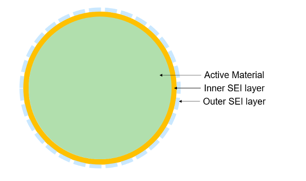
The SEI layer is made up of an inner and an outer layer. The inner layer forms directly on the anode, consists mainly of organic compounds (LiF, Li2O, Li2CO3), and is ionically conductive, electrically insulating, and mechanically stable. The outer layer forms on top of the inner layer, consists mainly of organic compounds (ROCO2Li) and is less ionically conductive and more porous.
To model the inner SEI layer in the Battery Single Particle block, set the Inner SEI layer
modeling method parameter to Diffusion-limited SEI
growth. You can specify the thickness of the SEI layer by setting the value
of the Thickness of SEI public variable in the Initial
Targets section.
To model the SEI layer, the block uses a single-layer interstitial-diffusion-limited model [5]. In this model, the neutral lithium interstitials diffuse through the previously formed SEI layer and react with the electrolyte to form more SEI. This figure shows the growth process and the reaction at the interface between the lithium and an ethylene carbonate (EC) electrolyte.
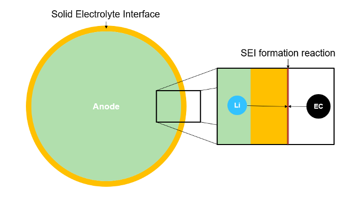
In this model, the reaction speed is so high that you can neglect it in the calculations. Additionally, the model considers the concentration of elementary lithium at the boundary between the SEI and electrolyte to be equal to 0.
The block calculates the current density of the lithium interstitial by using Fick's law,
where:
jSEI is the current density of the lithium interstitial.
F is Faraday's constant.
DSEI is the temperature-adjusted diffusion coefficient of the SEI. The block uses the value of the Diffusion coefficient of SEI parameter to calculate this value.
cn,max is the lithium concentration is the concentration at the surface of the anode.
cSEI,max is the lithium concentration in the SEI at the interface to the electrolyte.
LSEI is the thickness of the SEI and is equal to the value of the Thickness of SEI public variable in the Initial Targets section.
This equation defines the change of the SEI thickness over time,
where:
Mv is the molar volume and is equal to the value of the Molar volume of SEI parameter.
s is the stoichiometric coefficient and is equal to the value of the Stoichiometric coefficient in SEI parameter.
The block considers the additional overpotential due to the ionic conduction of the lithium ions through the SEI as an ohmic overpotential relative to the ionic conductivity,
where:
Ibatt is the battery current.
a is the interface area of the anode and determines how much surface area is available for reactions. The value of a depends on the volume of active material, its distribution across the electrode area, and the geometric characteristics of the particle.
λ is the temperature-adjusted conductivity of the SEI. The block uses the value of the Conductivity of SEI parameter to calculate this value.
Current Collector Resistance
This block models the current collector resistance as a single resistance. You can set the current collector resistance by specifying the Current collector resistance parameter.
Cell Voltage
To model the cell voltage, this block considers the potentials at the surfaces of each electrode, the overpotentials, and the voltage loss due to the current collector resistance by using the equation
where:
ocp+(c+surface,relative) is the open-circuit potential for the concentration at the surface of the cathode particle.
ocp-(c-surface,relative) is the open-circuit potential for the concentration at the surface of the anode particle.
ηdiffusion,ε is the mass transport overpotential in the electrolyte.
ηohmic,ε is the ohmic overpotential in the electrolyte.
ηkinetic,s is the charge transfer overpotential in the electrodes.
η-ohmic is the ohmic overpotential in the anode.
η+ohmic is the ohmic overpotential in the cathode.
Ibatt is the battery current.
RCurrentCollector is the resistance of the current collector.
ηohmic,SEI is the ohmic overpotential due to the ionic conduction of the lithium ions through the SEI. (since R2026a)
You can parameterize the open-circuit potential as table data by using normalized or absolute stoichiometry breakpoints:
If you set the Stoichiometry breakpoints specification parameter to
Normalized, you specify the open-circuit potentials normalized to the relative stoichiometry by setting the Anode open-circuit potential, Cathode open-circuit potential, and Normalized stoichiometry breakpoints parameters. The stoichiometry breakpoints are identical for both the anode and the cathode.If you set the Stoichiometry breakpoints specification parameter to
Absolute, you specify the open-circuit potentials normalized to the absolute stoichiometry. With this option, you can specify the stoichiometry breakpoints for the anode and the cathode independently by setting the Absolute anode stoichiometry breakpoints and Absolute cathode stoichiometry breakpoints parameters. (since R2025a)
To calculate the relative concentration, the block considers the maximum concentration and the maximum and minimum stoichiometry of each electrode. The Anode maximum ion concentration and the Cathode maximum ion concentration parameters represent the theoretically possible maximum concentration of each electrode. To obtain the achievable maximum and minimum concentrations, the block multiplies the values of these parameters with the value of the Anode maximum stoichiometry, Anode minimum stoichiometry, Cathode maximum stoichiometry, and Cathode minimum stoichiometry parameters, respectively. Then, the block calculates the relative concentration by using the equation
where:
cs,max is the maximum concentration.
Nmax is the maximum stoichiometry.
Nmin is the minimum stoichiometry.
Effective Electrolyte Properties
Set the values of these parameters based on the microstructure of the porous electrodes you want to model:
Diffusion coefficient of electrolyte — Set this parameter to the value of the diffusion coefficient of the electrolyte that influences the mass transport in the electrolyte.
Electrolyte conductivity — Set this parameter to the value of the conductivity of the electrolyte.
To model this dependency, this block uses the Bruggeman correlation,
where:
φε is the volume fraction of the electrolyte. This value is equal to the value of the Volume fraction of electrolyte in anode, Volume fraction of electrolyte in separator, and Volume fraction of electrolyte in cathode parameters, accordingly.
α is the Bruggeman exponent. This value is equal to the value of the Anode Bruggeman exponent, Separator Bruggeman exponent, and Cathode Bruggeman exponent parameters, accordingly.
Thermal
The block considers the temperature constant across the cell. These block parameters depend on the temperature of the cell:
Diffusion coefficient of anode active material and Diffusion coefficient of cathode active material— These parameters are the diffusion coefficients of electrodes that influence the mass transport in the electrodes.
Diffusion coefficient of electrolyte — This parameter is the diffusion coefficient of electrolyte that influences the mass transport in the electrolyte.
Electrolyte conductivity — This parameter is the conductivity of the electrolyte.
Anode conductivity and Cathode conductivity — These parameters are the conductivity of the electrodes.
Charge transfer rate constant for Anode and Charge transfer rate constant for Cathode — These parameters are the charge transfer rate constants of the electrodes.
Diffusion coefficient of SEI — This parameter is the diffusion coefficient of the SEI that influences the current density of the lithium interstitial. (since R2026a)
Conductivity of SEI — This parameter is the conductivity of the SEI. (since R2026a)
To calculate the temperature-adjusted values of these parameters, the block uses the Arrhenius equation,
where:
Parameterblock is the value of the temperature-dependent parameters.
Ea is the activation energy and is equal to the value of the activation energy parameters in the Thermal settings.
Tref is the value of the Arrhenius reference temperature parameter.
T is the battery temperature.
Heat Generation of Battery
This block models the battery as a lumped thermal mass. The single-particle model calculates the irreversible heat generation that the overpotentials cause in the battery by using this equation:
Qfaulted is the heat generated by the increased resistance when the Battery Single Particle block is faulted. (since R2025a)
Model Faults
Since R2025a
To model a fault in the Battery Single Particle block, in the Faults section, click Add fault next to the fault that you want to model. For more information about fault modeling, see Fault Behavior Modeling and Fault Triggering.
The Battery Single Particle block models the fault as an open-circuit cell when the additional series-connected resistance is high (greater than 1000 ohm) or when there is an abnormal internal resistance.

You specify how and when faults occur by using the Trigger Type parameter.
If you set the Trigger Type parameter to
Timed, the Battery Single Particle block triggers fault events when the
simulation time reaches the value you specify for the Trigger fault at
time parameter.
If you set the Trigger
Type to Conditional, you can choose whether faults
in the Battery Single Particle block are reversible (since R2025a). To model irreversible faults, click
Open fault properties to open the Property Inspector and select the
Trigger stays on once activated parameter. The block enters the faulted
state when the trigger condition becomes true for the first time and remains in the faulted
state for the rest of the simulation. To model reversible faults, clear the Trigger
stays on once activated parameter. The block enters the faulted state when the
trigger condition is true and enters the unfaulted state when the trigger condition is
false.
For more information about adding faults to blocks and specifying fault triggers, see Introduction to Simscape Faults.
Public Variables
You can use the Probe block to access these variables in the Battery Single Particle block. The units are the default values.
anodeElectrolyteOverpotential— Sum of the potential at the surface of the particle and the charge transfer overpotential in the anode, in volts. (since R2026a)anodeModel.intercalationCurrentDensity— Ratio between the anode current density and the active surface area per volume fraction, in A*m^2. (since R2026a)anodeModel.averageStoichiometry— Average stoichiometry in the anode.anodeModel.massTransportOverpotential— Mass transport overpotential, in volts.anodeModel.normalizedAverageStoichiometry— Average stoichiometry normalized to the minimum and maximum values.anodeModel.normalizedSurfaceStoichiometry— Surface stoichiometry normalized to the minimum and maximum values.anodeModel.ohmicOverpotential— Ohmic overpotential of the anode, in volts.anodeModel.shellConcentration— Concentration of the modeled shells, in mol/m^3. The number of shells is equal to the value of the Anode Shell Count parameter.anodeModel.shellStoichiometry— Stoichiometry of the modeled shells. The number of shells is equal to the Anode Shell Count parameter.anodeModel.surfaceConcentration— Concentration at the surface of the particle, in mol/m^3.anodeModel.surfacePotential— Potential at the surface of the particle, in volts.anodeModel.temperatureAdjustedConductivity— Conductivity adjusted to the battery temperature, in S/m.anodeModel.temperatureAdjustedDiffusionCoefficient— Diffusion coefficient adjusted to the battery temperature, in m^2/s.averageElectrolyteConcentration— Average concentration in the particle, in mol/m^3.batteryCurrent— Total current measured through the battery terminals, in amperes.batteryTemperature— Battery average temperature that the block uses for the table lookup of resistances and open-circuit voltage. If you set the Thermal model parameter toConstant temperature, thebatteryTemperaturevariable is equal to the specified temperature value. If you set the Thermal model parameter toLumped thermal mass, thebatteryTemperaturevariable is a differential state that varies during the simulation.batteryVoltage— Battery terminal voltage, or the voltage difference between the positive and the negative terminals, in volts.cathodeModel.averageStoichiometry— Average stoichiometry in the cathode.cathodeModel.intercalationCurrentDensity— Ratio between the cathode current density and the active surface area per volume fraction, in A*m^2. (since R2026a)cathodeModel.massTransportOverpotential— Mass transport overpotential, in volts.cathodeModel.normalizedAverageStoichiometry— Average stoichiometry normalized to the minimum and maximum values.cathodeModel.normalizedSurfaceStoichiometry— Surface stoichiometry normalized to the minimum and maximum values.cathodeModel.ohmicOverpotential— Ohmic overpotential of the cathode, in volts.cathodeModel.shellConcentration— Concentration of the modeled shells, in mol/m^3. The number of shells is equal to the value of the Anode Shell Count parameter.cathodeModel.shellStoichiometry— Stoichiometry of the modeled shells. The number of shells is equal to the Anode Shell Count parameter.cathodeModel.surfaceConcentration— Concentration at the surface of the particle, in mol/m^3.cathodeModel.surfacePotential— Potential at the surface of the particle, in volts.cathodeModel.temperatureAdjustedConductivity— Conductivity adjusted to the battery temperature, in S/m.cathodeModel.temperatureAdjustedDiffusionCoefficient— Diffusion coefficient adjusted to the battery temperature, in m^2/s.electrolyteModel.anodeOverpotential— Anode overpotential, in volts. (since R2026a)electrolyteModel.averageConcentration— Average concentration in the electrolyte across the whole cell, in mol/m^3.electrolyteModel.averageConcentrationAnode— Average concentration in the electrolyte inside the anode, in mol/m^3.electrolyteModel.averageConcentrationCathode— Average concentration in the electrolyte inside the cathode, in mol/m^3.electrolyteModel.averageConcentrationSeparator— Average concentration in the electrolyte inside the separator, in mol/m^3.electrolyteModel.concentrationAnode— Concentration of the modeled layers of the electrolyte in the anode, in mol/m^3. The number of elements is equal to the Electrolyte layer count of anode parameter.electrolyteModel.concentrationCathode— Concentration of the modeled layers of the electrolyte in the cathode, in mol/m^3. The number of elements is equal to the Electrolyte layer count of cathode parameter.electrolyteModel.concentrationSeparator— Concentration of the modeled layers of the electrolyte in the separator, in mol/m^3. The number of elements is equal to the Electrolyte layer count of electrolyte parameter.electrolyteModel.volumetricCurrentDensityAnode— Current density in the anode, in A/m^3.electrolyteModel.volumetricCurrentDensityCathode— Current density in the cathode, in A/m^3.electrolyteModel.diffusionCoefficientAnode— Temperature-adjusted effective diffusion coefficient of the electrolyte in the anode, in m^s/s.electrolyteModel.diffusionCoefficientCathode— Temperature-adjusted effective diffusion coefficient of the electrolyte in the cathode, in m^s/s.electrolyteModel.diffusionCoefficientSeparator— Temperature-adjusted effective diffusion coefficient of the electrolyte in the separator, in m^s/s.electrolyteModel.conductivityAnode— Temperature-adjusted effective conductivity of the electrolyte in the anode, in S/m.electrolyteModel.conductivityCathode— Temperature-adjusted effective conductivity of the electrolyte in the cathode, in S/m.electrolyteModel.effectiveConductivitySeparator— Temperature-adjusted effective conductivity of the electrolyte in the separator, in S/m.electrolyteModel.massTransportOverpotential— Mass transport overpotential of the electrolyte, in volts.electrolyteModel.ohmicOverpotential— Ohmic overpotential of the electrolyte, in volts.electrolyteModel.temperatureAdjustedConductivity— Temperature-adjusted conductivity of the electrolyte, in S/m.electrolyteModel.temperatureAdjustedDiffusionCoefficient— Temperature adjusted diffusion coefficient of the electrolyte, in m^s/s.heatGenerationRate— Total battery heat generation rate, in watts. The block calculates the heat generation rate by adding the resistive losses and the reversible heating contributions.irreversiblePlateMaterial— Generated plated lithium material that is irreversible, in mol. This variable is the Amount of irreversible plated material in the Initial Targets section. (since R2026a)power_dissipated— Resistive heat generation rate or dissipated power, in watts.reactionKineticsModel.chargeTransferOverpotential— Charge transfer overpotential of the anode, in volts. (since R2026a)reactionKineticsModel.chargeTransferOverpotential— Charge transfer overpotential of the battery, in volts.reactionKineticsModel.exchangeCurrentDensityAnode— Exchange current density in the anode, in C/(m^2*s).reactionKineticsModel.exchangeCurrentDensityCathode— Exchange current density in the cathode, in C/(m^2*s).reactionKineticsModel.temperatureAdjustedChargeTransferRateAnode— Temperature-adjusted charge transfer rate constant for the anode, in m^(5/2)/(mol^(1/2) * s).reactionKineticsModel.temperatureAdjustedChargeTransferRateCathode— Temperature-adjusted charge transfer rate constant for the cathode, in m^(5/2)/(mol^(1/2) * s).reversiblePlateMaterial— Generated plated lithium material that is reversible, in mol. This variable is the Amount of reversible plated material in the Initial Targets section. (since R2026a)stateOfCharge— Battery state of charge obtained from Coulomb counting.thermalModel.batteryTemperature— Temperature of the battery, in K.thermalModel.cellTemperature— Temperature output by the cell.thermalModel.heatDissipationRate— Heat dissipation rate of the battery, in watts.thermalModel.heatGeneration— Heat that the battery generates, in watts.thermalModel.thermalMass— Thermal mass of the battery, in J/K.thicknessSEI— Thickness of the SEI, in m. (since R2026a)
Examples

Examine Effects of Diffusion Coefficient and Volume Fraction on Battery Terminal Voltage
How the diffusion coefficient and the volume fraction of the electrode active material of a Battery Single Particle block affect the battery terminal voltage.
Ports
Conserving
Parameters
References
[1] Prada, E., D. D. Domenico, Y. Creff, J. Bernard, V. Sauvant-Moynot, and F. Huet. “Simplified Electrochemical and Thermal Model of LiFePO4-Graphite Li-Ion Batteries for Fast Charge Applications.” Journal of The Electrochemical Society 159, no. 9 (August 2012): A1508–A1519. https://doi.org/10.1149/2.064209jes.
[2] Kemper, P. and D. Kum. “Extended Single Particle Model of Li-Ion Batteries Towards High Current Applications”. In 2013 IEEE Vehicle Power and Propulsion Conference (VPPC), 1–6, 2013. https://doi.org/10.1109/VPPC.2013.6671682.
[3] Weaver, T., A. Allam, and S. Onori. “A Novel Lithium-Ion Battery Pack Modeling Framework - Series-Connected Case Study.” In 2020 American Control Conference (ACC), 365–372. Denver, CO, USA: IEEE, 2020. https://doi.org/10.23919/ACC45564.2020.9147546.
[4] Brodsky Ringler, Polina, Matthew Wise, Prashanth Ramesh, Jung Hyun Kim, Marcello Canova, Chulheung Bae, Jie Deng, and Heechan Park. 2023. "Modeling of Lithium Plating and Stripping Dynamics during Fast Charging" Batteries 9, no. 7: 337. https://doi.org/10.3390/batteries9070337
[5] Single, Fabian, Latz, Arnulf, and Horstmann, Birger. "Identifying the Mechanism of Continued Growth of the Solid–Electrolyte Interphase". ChemSusChem, vol. 11, no. 12, June 2018, pp. 1950–55. DOI.org (Crossref), https://doi.org/10.1002/cssc.201800077.