Integrate Antenna Array into MIMO Transmitter
R2026bThis example shows how to integrate a circular patch microstrip antenna and 8-element linear array at 27 GHz into a MIMO transmitter for system-level RF simulation.
To do this, first design a circular patch microstrip antenna using the design function, then arrange 8 elements into a linear array spaced for 27 GHz operation.
patchAntenna = design(patchMicrostripCircular, 27e9);
patchArray = design(linearArray(Element=patchAntenna), 27e9, patchAntenna);
Configure the array geometry. Set the ground plane dimensions to match the physical constraints of the 27 GHz design. Reduce the patch radius to 3 mm to better center the resonance at 27 GHz.
patchArray.Element.GroundPlaneLength = 0.007;
patchArray.Element.GroundPlaneWidth = 0.01;
patchArray.Element.Radius = 0.003;
patchArray.NumElements = 8;
patchArray.Tilt = -90; % Orient array broadside along the z-axis
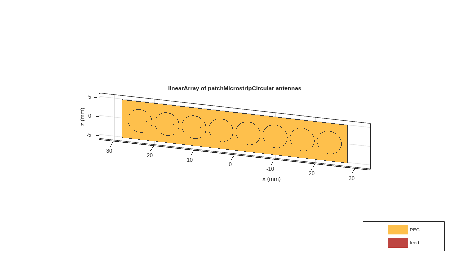
Visualize the array geometry to confirm the element placement.
figure;
show(patchArray)
view([-165 25])
Analyze Array Radiation and Impedance
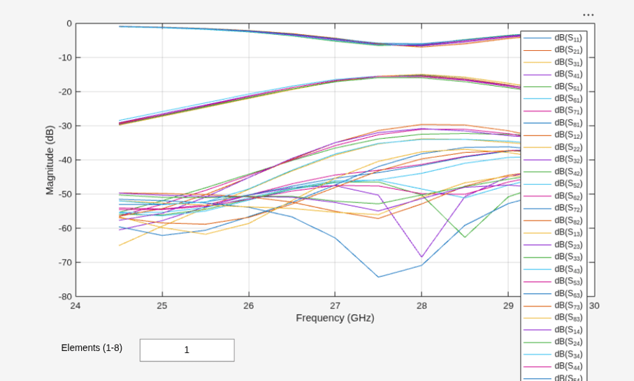
To verify the array meets the design requirements, analyze the radiation pattern at 27 GHz, the impedance across the operating band (24.5-29.5 GHz), and the S-parameters showing mutual coupling between elements.
pattern(patchArray, 27e9);
freqRange = (24.5:0.5:29.5)*1e9;
impedance(patchArray, freqRange)
rfplot(sparameters(patchArray, freqRange));
Save Antenna Data for Later Steps
Save the antenna characterization data for use in system-level integration. This data will also be used in Design Analog Beamsteering for MIMO Transmitter.
Reconfigure the single-element antenna to match the array element properties, then extract its radiation pattern. This pattern can be used to build a phased.CustomAntennaElement for steering vector computation.
patchAntenna.Radius = 0.003;
patchAntenna.Tilt = -90;
p = pattern(patchAntenna, 27e9);
Extract the array S-parameters at the center frequency. The Antenna block uses these to model mutual coupling between elements.
s = sparameters(patchArray, 27e9);
save("antennaData.mat", "s", "p", "patchArray")
Integrate Antenna Array into System-Level Simulation
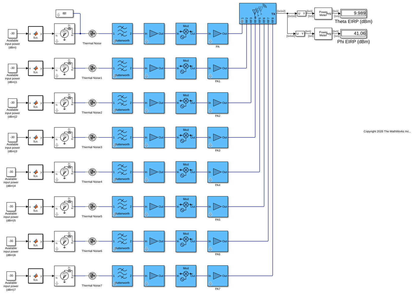
The model loads antennaData.mat at startup (via its PreLoadFcn callback), which places patchArray in the base workspace. The Antenna block uses patchArray directly as its antenna object, enabling full-wave EM-based modeling of S-parameters (near-field coupling) and embedded element patterns (far-field coupling).
The output power is reduced compared to the ideal antenna model due to impedance mismatch (the antenna is not exactly 50 Ohm). The circular patch transmits power along two polarization components, enabling accurate modeling of polarization mismatches when adding a channel and receiver.
open_system("TXmodel_3")
sim("TXmodel_3")
ans =

  Simulink.SimulationOutput:
                   tout: [401x1 double]

     SimulationMetadata: [1x1 Simulink.SimulationMetadata]
           ErrorMessage: [0x0 char]
See Also
Model RF Systems with Antenna Arrays Using RF Blockset Antenna Block

