Edit Imported S-Parameter Data
This example shows how you can check and modify the S-Parameter data using the Serial Link Designer app. An example S-Parameter file with bad data is imported and analyzed using the tools available in the S-Parameter Checklist dialog box in the Serial Link Designer app.
Create New Project
Open the Serial Link Designer app.
serialLinkDesigner
Create a new project by selecting File > New Project. In the newly opened dialog box, name the project as edit_sparameter, the interface as serdes, and the schematic sheet as channel. The Pre-Layout Analysis tab shows the blank schematic sheet.
A custom S-Parameter data file (example.s4p) is attached as supporting file to this example. This file represents PCB traces on a board. Download the Touchstone® (.s4p) files. To import the S-Parameter data, select Libraries > Import S-Parameter. Browse to the location where you saved the downloaded file and import the file. This launches the Edit S-Parameter Port Maps dialog box with two warnings. Ignore the warning that pops up for now, the example explores them in detail.
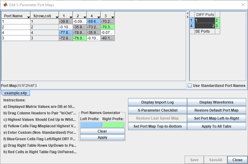
Use S-Parameter Checklist to Analyze S-Parameter Data
Click on the S-Parameter Checklist button on the Edit S-Parameter Port Maps dialog box to launch the S-Parameter Checklist dialog box. The S-Parameter Checklist dialog box has two panels with synchronized views. On the right are the frequency/time domain plots and a text editor. The left panel contains data and explanations of the plots.
First, look at the import log information in the left panel. The warnings indicate that there is no DC value in the S-Parameter file and that the port mapping algorithm found inconsistent data when trying to determine which ports go on the left of the symbol and which ports go on the right of the symbol.
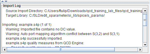
If you look at the File Editor tab in the right panel you can see that the lowest frequency point is 50MHz in the S-Parameter file. This is why the import log reported the no DC value warning.
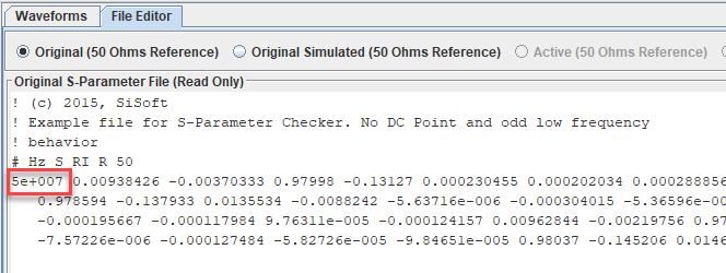
The warning about the port mapping algorithm is from the comparison of the 50MHz data in the file that is used to determine the pinout of the schematic symbol. This is due to the odd nature of the data in this S-Parameter file at low frequencies.
View Insertion Loss at Low Frequency
Click on the SE_Insertion_Loss tab at the left panel to take a look at the through path (insertion loss) data. Zoom in at lower frequencies. You can see there is some non-passive behavior and non-reciprocal behavior.

Enforce passivity to investigate further. Select Quality Enforcement > Make Passive from the toolstrip. To refresh the data, go back to the Visual_Inspection tab. Select Enable Editing at the top of the File Editor. Then click on the Refresh Checklist Data button on the bottom of the right panel. Refresh the data and look at the SE_Insertion_Loss tab again. To see only the refreshed data, deselect the Active (50 Ohms Reference) option above the node list.
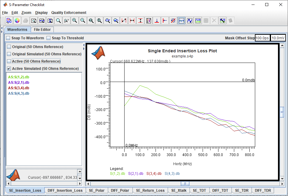
The insertion loss data is now all passive, but there are still some strange issues at the lowest frequencies. The loss is greater at DC than at low frequencies. This does not make sense for PCB traces.
Delete Bad Low Frequency Data
To see if it the insertion loss behavior is caused by bad low frequency data you can delete the low frequency points from the file. Go back to the Visual_Inspection tab. In the right panel select the S-Parameter data for frequencies less than 500MHz and delete the data points. Save the changes by clicking the Save File button.
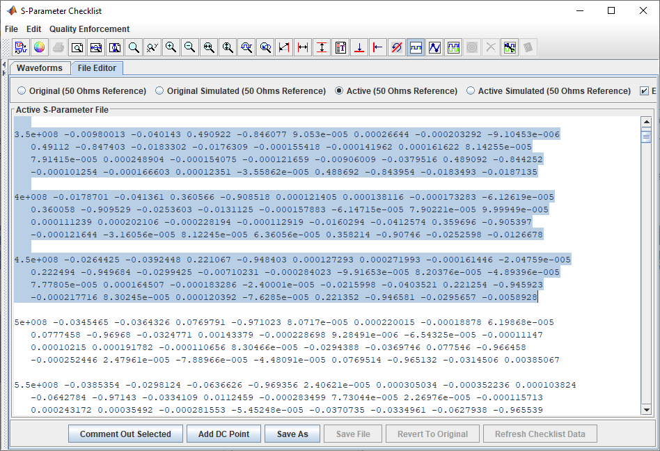
Refresh the checklist data and go back to the SE_Inserion_Loss tab in the left panel.The loss is now increasing with frequency. The only issue is that the S(1,2) and S(4,3) data do not have the same DC point. This is because the Serial Link Designer app is extrapolating the data to get a DC value and the data it is extrapolating from are not the same for the two paths.

Add DC Point
On the assumption that the lengths and thus the DC values should be the same for both paths you can add a DC point manually. Go back to the Visual_Inspecion tab in the left panel. Right click on the text editor in the right panel and select Add DC Point. On the Add DC Point dialog box that opens select Trace Geometry Based Resistance Calculation. Change the Trace Length to 2600 mils. The length is an estimate based on the maximum through path delay value that is in the S-Parameter file Metrics section of the left panel and an assumed delay of 180ps/in for stripline.
Click Insert DC Point, then save the file and refresh the checklist data. Go back to the SE_Insertion_Loss tab in the left tab. Now the insertion loss is increasing with frequency and all the data has the same DC point.
