GPS Data Decode
This example shows how to perform bit and frame synchronization and decode the legacy GPS navigation (LNAV) data as per IS-GPS-200 [1].
Introduction
This figure shows the various operations in a typical GPS receiver. The GPS Receiver Acquisition and Tracking example describes the operations shown in red blocks in this figure. This example focuses on the green blocks. The GPS LNAV data transmits at a rate of 50 bits per second. In other words, each bit takes 20 milliseconds for transmission. The tracking module in the receiver tracks the phase shift, frequency offset, and delay between the visible GPS satellites and the receiver. For tracking, the received baseband signal is integrated to calculate the tracking metrics [2]. During tracking, if the integration happens over a bit transition, then the effective integrated value decreases because the bit values vary. Hence, the first step in data decoding is to find the exact bit transition boundary. Next, use the frame synchronization module to calculate the frame boundaries, which are required for navigation data decoding. Once the frame boundary is known, perform data decoding to get the received navigation data from a satellite. Data decoding from each tracking output channel must be done independently. This example shows how to decode data for a single satellite.
This example is divided into three parts.
Bit Synchronization — Find the bit boundary in the output of the tracking loop.
Frame Synchronization — Find the frame boundary in the demodulated bits.
Decode GPS LNAV Data — Decode the bits to get the timing, ephemeris, almanac, and other data needed to estimate the receiver position.
To perform any of these steps, tracking results (time and frequency synchronized waveforms) are required. By default, this example uses 125 subframes of data from satellite PRN ID 7, which are stored in trackedSignal.mat and attached to this example as a supporting file. The samples are collected at a signal to noise ratio (SNR) of -23 dB. For more information on acquiring and tracking a GPS signal, see GPS Receiver Acquisition and Tracking.
Load the samples that the tracking loops output. Each sample in this array has a duration of 1 millisecond. The data type of the tracking loop output is floating-point double precision. To conserve storage, the MAT file stores the data in fixed point format with 1 sign bit, 1 bit for the integer part, and 6 bits for the fractional value. Convert the fixed-point data back into floating-point double format.
load trackedSignal.mat
trackedSignal = double(trackedSignal)/(2^6); % Convert fixed-point number to real value
Bit Synchronization
For the LNAV data, once tracking of the C/A-codes is complete, each code block with a C/A-code boundary of 1 millisecond duration is known. This 1 millisecond code block is integrated in the tracking module to get 1 sample. Each data bit consists of 20 such samples corresponding to 20 milliseconds. To get the bit boundary in each block of 20 milliseconds, flag the location (within this 20 millisecond block) that has the maximum number of transitions [2].
Call the gnssBitSynchronize function to find where the bit transition occurs. Because C/A-codes sit on the quadrature branch of the waveform, consider only the imaginary part of the signal. The gnssBitSynchronize function estimates the data transition and gives the index of maximum number of transitions to indicate start of bit location within 20 samples. The numAveragingBits variable controls the length of the window to search for the data transitions. Because each data bit consists of 20 samples, when you set numAveragingBits to 100, a window of 20*100 = 2000 samples are used to decide the bit transition boundary.
numCACodeBlocksPerBit = 20;
numAveragingBits = 100;
numAveragingSamples = numCACodeBlocksPerBit*numAveragingBits;
[maxTransitionLocation, transitionValues] = ...
    gnssBitSynchronize(imag(trackedSignal(1:numAveragingSamples,1)),numCACodeBlocksPerBit);
maxTransitionLocation
maxTransitionLocation = 2
bar(transitionValues)
xlabel('Sample Index')
ylabel('Number of Transitions')
title('Bit Transitions Chart')
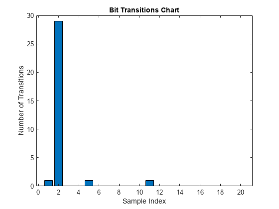
In the above figure, observe that the highest number of transitions occur at the location of bit transition.
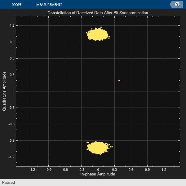
Consider block of 20 samples from the location of the bit transition and integrate every 20 samples to generate soft log-likelihood ratios (LLRs). Get the bit values from the soft LLR values.
[samples,leftout] = buffer(trackedSignal(maxTransitionLocation:end,1),numCACodeBlocksPerBit);
softbits = mean(samples).';
bits = imag(softbits)<0;
rxconstellation = comm.ConstellationDiagram(1,"ShowReferenceConstellation",false);
rxconstellation.Title = "Constellation of Received Data After Bit Synchronization";
rxconstellation(softbits(:))
Frame Synchronization
Frame synchronization, which determines the exact starting and ending points of a subframe. This information is necessary for the data decoder to process data.
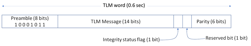
Each subframe begins with a known 8-bit preamble. The frame synchronization module searches for this 8-bit sequence. Because an 8-bit sequence is small, the same sequence can occur somewhere else within the data. After detecting the 8-bit preamble, decode the first and second words of the subframe. If the parity checks pass, then decode the time of week present in the handover word [1] and the subframe ID. If the time of week and the subframe ID agree, declare a successful frame boundary detection. Cycle slip in the tracking loops is possible, so continuous processing of the frame synchronization ensures that the decoder always works with an exact subframe [2]. This figure shows the telemetry word and handover word in a GPS LNAV data subframe.
Initialize the frame synchronization System object™. This object returns the frame synchronized subframes in each column. Send all of the data through this object. This object also works when each subframe of data is passed through it iteratively.
framesync = HelperGPSLNAVFrameSynchronizer;
[syncidx, rxsubframes, subframeIDs] = framesync(bits);
syncidx
syncidx =
1
numSubframes = size(rxsubframes,2)
numSubframes =
124
subframeIDs
subframeIDs = 1×124

     1     2     3     4     5     1     2     3     4     5     1     2     3     4     5     1     2     3     4     5     1     2     3     4     5     1     2     3     4     5     1     2     3     4     5     1     2     3     4     5     1     2     3     4     5     1     2     3     4     5
Decode GPS LNAV Data
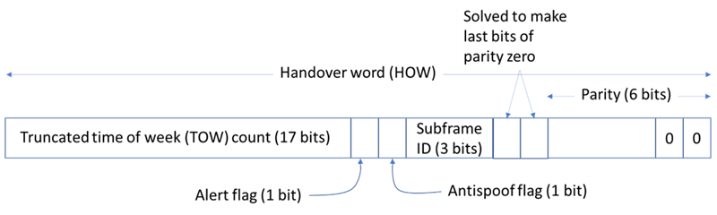
The GPS LNAV data is transmitted in 1500-bit length frames. Each frame consists of five subframes of 300 bits each. Because the data rate is 50 bits per second, transmitting each subframe takes 6 seconds and transmitting each frame takes 30 seconds. Each subframe consists of 10 words with 30 bits (24 data bits and 6 parity bits) in each word. The GPS data contains information regarding the clock and the position of the satellites. This figure shows the frame structure of the LNAV data.

This example processes each subframe independently.
cfg = struct;
accuParityChecks = zeros(numSubframes,10);
for isubframe = 1:numSubframes
    [cfg,parityChecks] = HelperGPSLNAVDataDecode(rxsubframes(:,isubframe),cfg);
    accuParityChecks(isubframe,:) = parityChecks;
end
numWordsInError = numel(accuParityChecks) - nnz(accuParityChecks)
numWordsInError =
0
The transmitted configuration properties and the decoded configuration properties must have same values. These are the decoded configuration parameters.
cfg
cfg = struct with fields:
                       SignalType: "LNAV"
                         Preamble: 139
                       TLMMessage: 0
                           HOWTOW: 124
                    AntiSpoofFlag: 0
                        CodesOnL2: "P-code"
                      L2PDataFlag: 0
                         SVHealth: 0
                 IssueOfDataClock: 0
                            URAID: 0
                       WeekNumber: 101
           GroupDelayDifferential: 0
    SVClockCorrectionCoefficients: [3×1 double]
             ReferenceTimeOfClock: 0
              SemiMajorAxisLength: 2.6560e+07
             MeanMotionDifference: 0
                  FitIntervalFlag: 0
                     Eccentricity: 0.0200
                      MeanAnomaly: 0
         ReferenceTimeOfEphemeris: 0
          HarmonicCorrectionTerms: [6×1 double]
             IssueOfDataEphemeris: 0
              IntegrityStatusFlag: 0
                ArgumentOfPerigee: -0.5200
             RateOfRightAscension: 0
         LongitudeOfAscendingNode: -0.8400
                      Inclination: 0.3000
                  InclinationRate: 0
                  AgeOfDataOffset: 0
        NMCTAvailabilityIndicator: 0
                          NMCTERD: [30×1 double]
                       Ionosphere: [1×1 struct]
                              UTC: [1×1 struct]
                      TextMessage: 'This content is part o'
                        AlertFlag: 0
                       SubframeID: 4
                           DataID: [2×1 double]
                         SVPageID: 63
                          Almanac: [1×1 struct]
             ReferenceTimeUTCData: 0
      TimeDataReferenceWeekNumber: 101
              PastLeapSecondCount: 18
    LeapSecondReferenceWeekNumber: 101
     LeapSecondReferenceDayNumber: 1
            FutureLeapSecondCount: 18
                  AlmanacSVHealth: [0 0 0 0 0 0 0 0 0 0 0 0 0 0 0 0 0 0 0 0 0 0 0 0 0 0 0 0 0 0 0 0]
Further Exploration
This example performs frame synchronization, considering all subframes at a time. In practice, each subframe processing occurs in a loop whenever any new data is received. You can perform frame synchronization on every subframe independently. Also, this example does not update the bit synchronization status back to the tracking loop. You can also use the bit synchronization value to increase the phase locked loop (PLL) integration time to enhance the PLL performance at low SNR values.
Supporting Files
This example uses these helper files:
HelperGPSLNAVDataDecode.m— Decode the LNAV GPS data.HelperGPSLNAVFrameSynchronizer.m— Perform frame synchronization on the demodulated data.HelperGPSLNAVWordDecode.m— Decode each word of a subframe.
This example uses this data file:
trackedSignal.mat — Output of the tracking loop in the GPS Receiver Acquisition and Tracking example for satellite PRN ID 7
References
[1] IS-GPS-200, Rev: L. NAVSTAR GPS Space Segment/Navigation User Segment Interfaces. May 14, 2020; Code Ident: 66RP1.
[2] Elliott D. Kaplan and C. Hegarty, eds., Understanding GPS/GNSS: Principles and Applications, Third edition, GNSS Technology and Applications Series (Boston ; London: Artech House, 2017).