NavIC Receiver Positioning
This example simulates the Navigation with Indian Constellation (NavIC) signal generation and reception chain to estimate the location of the receiver. The example simulation consists of a multi-satellite scenario using a NavIC satellite RINEX (Receiver Independent Exchange) file, and calculates the Doppler shift and signal latency associated with a certain receiver position for all the satellites. The Doppler shift and latency values enable a realistic simulation by impairing the signal. The receiver modules process the ensemble of impaired signals in this order: acquisition, tracking, bit-synchronization, frame-synchronization, data decoding, and position estimation of the receiver.
Example Workflow
This section highlights the workflows that serve as the building blocks of this simulation. These points provides an overview of the waveform generation and propagation chain steps.
Using a RINEX file, simulate the NavIC constellation using the
satelliteScenarioobject.Calculate the Doppler shift and signal latency for all satellites at each of the simulation time points.
Configure the parameters of navigation data object, which includes ephemerides and clock parameters, using the RINEX file.
Obtain navigation data bits from a navigation data object.
Generate a NavIC waveform by spreading the navigation data and then multiplex the subcarrier signals using the interplex modulation. For more information on generating a NavIC waveform and using interplex modulation, see NavIC Waveform Generation and
interplexmod, respectively.Propagate the interplexed signal through a channel, which impairs each of satellite signals with the calculated Doppler shift, signal latency, and random noise.
Similarly, these are the steps of the receiver chain.
Use
gnssSignalAcquirerandgnssSignalTrackerobjects to acquire and track all transmitting satellites, respectively.Use
gnssBitSynchronizeto perform bit synchronization, that is, find the start position of the first valid bit in the received samples.Synchronize the subframe by matching the sync-code transmitted with each subframe.
Decode the navigation data from the detected subframes.
Calculate pseudoranges by estimating the transit time.
Estimate the receiver position using pseudoranges and satellite positions at the transmission time.
Initialize Simulation Parameters
Initialize the relevant simulation parameters.
Check the ShowVisualization check box to show the plots in simulation. You can enable WriteWaveformToFile to save the generated complex baseband waveform to a file, which you can use later with another receiver. WaveformType specifies the band for which to generate the waveform.
ShowVisualizations =true; WriteWaveformToFile =
false; WaveformType =
"NavIC L5";
A NavIC L5 or S band subframe is 12 seconds long. Initialize the simulation data duration as the total duration of the subframes to be transmitted. Note that a NavIC receiver requires 60 seconds or more of data to estimate the receiver position. If you aim to run complete simulation to estimate the receiver's position, set the duration to 60 seconds or more, as this is the minimum required for position estimation by a NavIC receiver.
However, if you want faster execution or have limited computational resources, you can set simulationDuration to any value less than 60 seconds since the NavICreceiverPositionProperties dataset is available. This dataset already includes the necessary data for position estimation, allowing you to conduct quicker simulations. Initialize the sampling rate for baseband waveform generation.
% Set this as a multiple of 12 for a simulation longer than 60 seconds.
simulationDuration = 3; % In seconds

% Set this value to define the sample rate of the generated waveform.
fs = 10e6;            % In Hz
This example processes data in chunks of 1 millisecond (ms). In other words, the example generates waveform of 1 ms, and then processes through the receiver chain at each step.
stepTime = 1e-3;                                 % In seconds
numSteps = (simulationDuration/stepTime) + 1;
Initialize the receiver position to model the waveform propagation channel based on its location. It is crucial to model the propagation delays accurately to simulate a NavIC receiver. This example models a stationary receiver, and does not support a moving receiver.
rxlat = 28.6329; % Delhi
rxlon = 77.2195;
rxalt = 100;
As delays are modeled in the propagation channel, a Global Navigation Satellite System (GNSS) receiver receives the actual signal after some delay. The typical delay for a NavIC signal is around 120 ms. Therefore, set an appropriate receiver wait time parameter to ensure the receiver captures a meaningful signal rather than just noise.
rxWaitTime = 149; % In msInitialize the parameters for the receiver functions. You need at least 4 tracking channels to track the minimum number of satellites required for estimating the position of the receiver.
% Initialize maximum number of tracking channels.
maxNumTrackingChannels = 8;

% Noise bandwidth of each of the tracking loops
PLLNoiseBW = 90;            % In Hz
FLLNoiseBW = 4;             % In Hz
DLLNoiseBW = 3;             % In Hz

% Bit synchronization parameters
numBitsForBitSync = 100;
numWaitingStepsForBitSync = 20*numBitsForBitSync;
rxcntr = 1;
Initialize the physical constants required for the simulation.
c = physconst("LightSpeed");            % Speed of light in m/sec
if strcmp(WaveformType,"NavIC L5")
    fc = 1176.45e6;                     % NavIC L5 band carrier frequency in Hz
else
    fc = 2492.028e6;                    %#ok<UNRCH> % NavIC S band carrier frequency in Hz
end
Dt = 12;                                % Directivity of the transmit antenna in dBi
DtLin = db2pow(Dt);
Dr = 4;                                 % Directivity of the receive antenna in dBi
DrLin = db2pow(Dr);
Pt = 50;                                % Typical transmission power of a GNSS satellite in watts
k = physconst("boltzmann");             % Boltzmann constant in Joules/Kelvin
T = 300;                                % Room temperature in Kelvin
Nr = k*T*fs;                            % Thermal noise power in watts
Configure Simulation
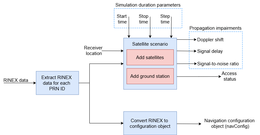
Set up the simulation using the simulation parameters and physical constants. The diagram outlines the simulation configuration of this section.
The simulation uses RINEX files to exchange satellite navigation data from various GNSS constellations. They contain data such as the ephemeris and clock corrections for visible satellites at different times. Because a satelliteScenario simulation requires only one data point per satellite, extract only the first data point for each PRN ID from the RINEX data. Use extracted data to add satellites to the scenario and create a navigation configuration object.
Parse the RINEX file to create a configuration object for navigation data generation.
% Specify the RINEX filename.
rinexFileName = "IITK00IND_R_20243400400_01H_MN.rnx";
rinexdata = rinexread(rinexFileName);
allNavicData = rinexdata.NavIC;

% Extract the navigation parameters for the available unique satellites.
[~,satIdx] = unique(allNavicData.SatelliteID);
navicData = sortrows(allNavicData(satIdx,:),1);

% Create a navigation data configuration object using the RINEX file.
navConfig = HelperNavICRINEX2Config(navicData);
Configure a scenario with the required navigation parameters using the corresponding RINEX file.
sc = satelliteScenario;
% Ensure that the time of week (TOW) value is 1 plus a multiple of the
% number of subframes so that the data for subframe 1 is always generated
% first.
[mintowc,locmintowc] = min([navConfig(:).TOWC]);
mintowc = ceil((mintowc-1)/4)*4 + 1;
[navConfig(:).TOWC] = deal(mintowc);

sc.SampleTime = stepTime;
sc.StartTime = HelperGNSSConvertTime(navConfig(locmintowc).WeekNumber,mintowc*12);
sc.StopTime = sc.StartTime + seconds(simulationDuration);

% Add the extracted satellites to the scenario.
[sc,sat] = HelperAddSatellite(sc,navicData);
Set up a receiver in the scenario. Calculate the Doppler shift and latency for all of the satellites.
rx = groundStation(sc,rxlat,rxlon,Altitude=rxalt,MaskElevationAngle=20); % Set up the receiver
ac = access(sat,rx);
acstats = accessStatus(ac);

% This example runs for a maximum of 2 minutes of data and access does not
% change for that duration. Thus, consider, the access status of only the
% first sample time.
satindices = find(acstats(:,1));
numSat = length(satindices);

if ~numSat
    error("No NavIC satellites are detected at the receiver's location. " + ...
        "Ensure that receiver is positioned within the NavIC operational " + ...
        "region and that the RINEX file includes visible satellites for this location.")
end

% Calculate the Doppler shift over time for all the visible satellites.
fShift = dopplershift(sat(satindices),rx,Frequency=fc);

% Calculate signal delays over time for all the visible satellites.
delays = latency(sat(satindices),rx);

PRNIDs = [navConfig(:).PRNID];
disp("Available satellites - " + num2str(PRNIDs(satindices)))
Available satellites - 2 6 9 10
Initialize the waveform writer object.
if WriteWaveformToFile == 1
    bbWriter = comm.BasebandFileWriter("NavICBBWaveform.bb",fs,0);
end
Initialize Waveform Generation Parameters
Specify the parameters required to generate a NavIC waveform. These parameters include signal properties specific to the NavIC standard.
% Set amplitude factor values for interplex modulation.
A1 = 2/3;
A2 = sqrt(2)/3;
A3 = sqrt(2)/3;

oneCACodeDuration = 1e-3;                          % Duration of one C/A-code block, which is equal to the stepTime of simulation
chipRate = 1.023e6;
oneBitduration = 20e-3;                            % Transmission rate for NavIC L5/S is 50bps, Thus, the time taken to
                                                   % transmit one bit is 20 ms.
frameDuration = 48;
numChipsPerCodeBlock = chipRate*oneCACodeDuration;
numCACodeBlocksPerBit = 20;

% Property for counting the received samples from each satellite.
sampleCntr = zeros(1,numSat);
rxistep = 1;                                       % receiver step counter
Initialize the spreading codes and System objects for the receiver chain.
% Find the spreading codes that correspond to the available satellites.
caCode = gnssCACode(PRNIDs(satindices),WaveformType);

% Initialize the signal acquisition and signal tracking objects.
sigAcquisition = gnssSignalAcquirer;
sigAcquisition.SampleRate = fs;
if strcmp(WaveformType,"NavIC L5")
    sigAcquisition.GNSSSignalType = "NavIC L5 C/A";
else
    sigAcquisition.GNSSSignalType = "NavIC S C/A"; %#ok<UNRCH>
end
sigTracker = gnssSignalTracker(GNSSSignalType=sigAcquisition.GNSSSignalType, ...
    SampleRate=fs,PLLNoiseBandwidth=PLLNoiseBW,FLLNoiseBandwidth=FLLNoiseBW,DLLNoiseBandwidth=DLLNoiseBW);

% Properties for storing the outputs of the tracking module.
trackedWave = zeros(numSteps - rxWaitTime,numSat);
trackInfo = struct("PhaseError",[],"PhaseEstimate",[],"FrequencyError",[],"FrequencyEstimate",[], ...
                "DelayError",[],"DelayEstimate",[]);

% Property for storing the outputs of bit synchronization.
bitlocation = zeros(maxNumTrackingChannels,1);

% Initialize the propagation channel object with the waveform sample rate.
gnssChannel = HelperGNSSChannel(RandomStream="mt19937ar with seed",SampleRate=fs);

% Set the random stream seed to control random bits generation.
rngObj = RandStream("mt19937ar","Seed",73);

% Set the first state of the receiver chain, which is the acquisition of the satellites
nxtState = "acquisition";
Generate Navigation Data Bits
Generate the NavIC navigation data bits from the RINEX data extracted using the HelperNavICRINEX2Config helper function. The encoder functions adhere to the NavIC standard and manage all encoding tasks, such as data interleaving and convolutional encoding.
The navigation data bits variable navData contains data bits for all subframes specified in the configuration object. The number of generated data frames is equal to the length of the subframe3MsgID or subframe4MsgID property of the navConfig configuration object. The encoder generates same number of frames for each PRN ID in the configuration object. You can increase or decrease the number of generated frames by adding or removing a valid message type ID from both the subframe3MsgID and subframe4MsgID properties of the navConfig configuration object.
navData = HelperNavICDataEncode(navConfig);
Transmit-Receive Loop
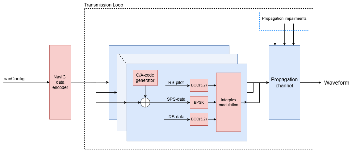
Generate a NavIC waveform for each millisecond of data. The transmitted signal consists of both the NavIC services:
Standard positioning services (SPS) — Available to the public for navigational purposes.
Restricted service (RS) — An authorized encrypted service, which is not public. The example generates these RS signals as random bits.
To form the final transmit signal, interplex the three signals (SPS-data, RS-data, and RS-pilot) as defined in the NavIC standard [1]. The system resamples the generated signal according to the specified sample rate fs, and then passes it through the propagation channel. The propagation channel impairs the signal with Doppler shift, signal delay, and noise, where the delay and Doppler shift values are derived from the satelliteScenario simulation.
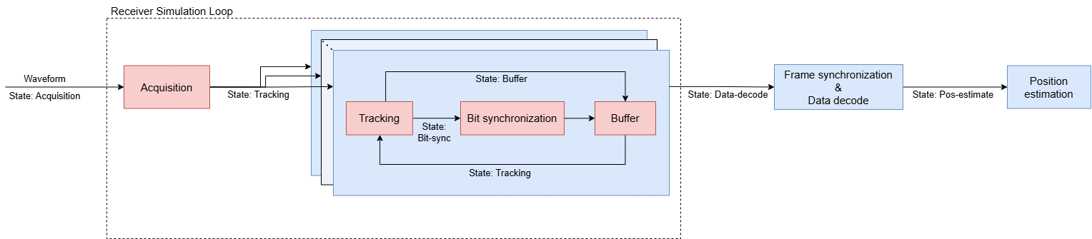
The last part of this processing loop implements a NavIC receiver. The receiver starts with signal acquisition after a number of steps, defined by rxWaitTime, have elapsed, ensuring that the receiver captures meaningful signal rather than pure noise due to the signal delays. These are the steps in the receiver chain.
Acquisition — Finds the visible satellites and provides the coarse Doppler frequency offset and timing offset.
Tracking — The acquisition module finds the coarse estimates and uses them to initialize the tracking loops. The tracking module in the GNSS receiver uses a phase-locked loop (PLL), frequency-locked loop (FLL), and delay-locked loop (DLL) to ensure precise positioning. The PLL maintains phase alignment, the FLL tracks frequency changes, and the DLL measures signal delay to calculate the distance.
Bit-synchronization — Once you have tracked enough samples, defined by the value of
numWaitingStepsForBitSync, thegnssBitSynchronizefunction synchronizes the samples to find the start of a complete data bit. A NavIC data bit consists of 20 C/A-code blocks. Thus, you synchronize the bits by finding the index of maximum transition among a set of 20 C/A-code blocks.Buffer — Indicates a storage state in the receiver chain. The buffer collects the tracked samples of all of the visible satellites until the end of the simulation.
This table provides gives details on the state-based behavior of the receiver. It lists all the five state-based behaviors of a GNSS receiver.
State | Action |
Acquisition | Start state of the receiver. Indicates the acquisition module of the receiver. |
Tracking | GNSS signal tracking module of the receiver. |
Bit-sync | Bit synchronization module. |
Data-decode | Frame synchronization and received data decoding module. |
Pos-estimate | Position estimation module. |
This diagram further illustrates each state-based behavior. The acquisition state is the initial state for the first waveform chunk of stepTime (1 ms) duration. After processing one chunk, the receiver sets a new state for the next waveform chunk and breaks out of the state machine. The next transmitted waveform chunk enters the receiver state machine with the previous state for further processing. This process continues until the entire waveform has been processed.
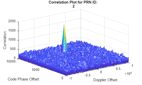
tic
for istep = 1:numSteps
    % Choose the bit index according to the specified start index and step
    % count.
    bitidx  = floor((istep-1)/numCACodeBlocksPerBit) + 1;
    SPSBits = xor(caCode,navData(bitidx,satindices));

    % Modulate the RS signal
    dummyRSP = repelem(repmat(randi(rngObj,[0,1],numChipsPerCodeBlock,1),numSat,1),2,1); % Random binary bits as data for RS-pilot
    dummyRSD = repelem(repmat(randi(rngObj,[0,1],numChipsPerCodeBlock,1),numSat,1),2,1); % Random binary bits as data for RS-data

    % Modulated SPS
    SPSmod = 1-2*double(SPSBits(:));

    % Rate-match the SPS signal with BOC modulated RS signals
    s2 = repelem(SPSmod,20,1);
    s3 = bocmod(dummyRSP,5,2);
    s1 = bocmod(dummyRSD,5,2);
    [bbwave_temp,eta] = interplexmod([s1,s2,s3],[A1 A2 A3]);
    bbwave = reshape(sqrt(2)*bbwave_temp,length(bbwave_temp)/numSat,numSat);

    % Resample according to the specified sample rate
    [upfac,downfac] = rat(fs/20.46e6);
    idx = 1:downfac:upfac*size(bbwave,1);
    iwave = bbwave(ceil(idx/upfac),:);

    % Introduce propagation channel effects to the transmitted signal
    gnssChannel.SignalToNoiseRatio = -10;
    gnssChannel.SignalDelay = delays(:,istep)';
    gnssChannel.FrequencyOffset = fShift(:,istep)';

    iTxWave = gnssChannel(iwave);

    % Optionally write the waveform to a file
    if WriteWaveformToFile == 1
        bbWriter(iTxWave)
    end

    if strcmp(nxtState,"exit")
        break;
    end

    % Receiver
    if istep > rxWaitTime
        while true
            switch(nxtState)
                case "acquisition"
                    % Initial synchronization
                    [acqd,corrval] = sigAcquisition(iTxWave,1:14);
                    acqIdx = acqd.IsDetected == 1;
                    detectedSatTable = sortrows(acqd(acqIdx,:));
                    PRNIDsToSearch = detectedSatTable.PRNID;
                    numRxSat = length(PRNIDsToSearch);
                    disp("The detected satellite PRN IDs: " + num2str(PRNIDsToSearch'))

                    if sum(acqIdx) > 3
                        % If three or more satellites are detected
                        sigTracker.InitialFrequencyOffset = detectedSatTable.FrequencyOffset;
                        sigTracker.InitialCodePhaseOffset = detectedSatTable.CodePhaseOffset;
                        sigTracker.PRNID = PRNIDsToSearch;
                        rxSamples = cell(numRxSat,1);
                        nxtState = "tracking";

                        if ShowVisualizations
                            % Correlation plot for first detected satellite
                            figure
                            mesh(-10e3:500:10e3,0:size(corrval,1)-1, corrval(:,:,PRNIDsToSearch(1)))
                            xlabel("Doppler Offset")
                            ylabel("Code Phase Offset")
                            zlabel("Correlation")
                            msg = ["Correlation Plot for PRN ID: " num2str(PRNIDsToSearch(1))];
                            title(msg)
                        end
                    else
                        % If acquisition fails, that is, less than three
                        % satellites are detected, the receiver state
                        % remains the same, which is acquisition.
                        nxtState = "exit";
                        break
                    end

                case "tracking"
                    [trackedWave(rxistep,:),trackInfo(rxistep)] = sigTracker(iTxWave);
                    if any(bitlocation)
                        % Once bit synchronization is complete, store the
                        % samples.
                        nxtState = "buffer";
                    elseif rxistep > numWaitingStepsForBitSync
                        % If enough samples are collected, move to bit
                        % synchronization state.
                        nxtState = "bit-sync";
                    else
                        % Exit the receiver machine. State remains
                        % "tracking" for next sample.
                        break
                    end
                case "bit-sync"
                    for isat = 1:numSat
                        [bitlocation(isat),numtr] = gnssBitSynchronize( ...
                            imag(trackedWave(1:numWaitingStepsForBitSync,isat)), ...
                            numCACodeBlocksPerBit);
                        rxSamples{isat} = trackedWave(bitlocation(isat):end,isat);
                        sampleCntr(isat) = rxistep - bitlocation(isat) + 1;
                    end
                    nxtState = "tracking";
                    break;
                case "buffer"
                    % Once bit synchronization is successful, the receiver
                    % machine switches between "tracking" and "buffer"
                    % states for each step
                    for isat = 1:numSat
                        sampleCntr(isat) = sampleCntr(isat) + 1;
                        rxSamples{isat}(sampleCntr(isat)) = trackedWave(rxistep,isat);
                    end
                    nxtState = "tracking";
                    break
            end
        end
    rxistep = rxistep + 1;
    end
    if ~mod(istep,1000)
        disp("Processed " + (istep/1000) + " sec of data at the receiver.")
    end
end
The detected satellite PRN IDs: 2 6 9 10
Processed 1 sec of data at the receiver.
Processed 2 sec of data at the receiver.
Processed 3 sec of data at the receiver.
toc
Elapsed time is 44.840264 seconds.
rxistep = rxistep - 1;
if WriteWaveformToFile
    % Release the waveform writer object
    release(bbWriter) %#ok<UNRCH>
end
if ShowVisualizations
    % Show the last 1000 received samples
    rxconstellation = comm.ConstellationDiagram(1,ShowReferenceConstellation=false, ...
        Title="Constellation diagram of signal at the output of tracking");
    rxconstellation(trackedWave(max(1,rxistep-999):rxistep,1)/rms(trackedWave(max(1,rxistep-999):rxistep,1)))
end

Decode Received Data
Synchronize the frames and decode the data of the received symbols. Frame synchronization is successful when the parts of the received samples match sync-code defined in the NavIC standard. The synchronization function provides the start index of a subframe in the received symbols, which is then used for data decoding.
Initialize Parameters
Initialize the parameters to for configuring the frame synchronization object and storing the decoded values.
syncCode = [1 1 1 0 1 0 1 1 1 0 0 1 0 0 0 0]';   % Synchronization code (sync-code) as defined in the NavIC standard
numSymPerSF = 600;
numStepPerSym = 20;
numStepsPerSF = numSymPerSF*numStepPerSym;
maxDetectLen = 3*numSymPerSF;                    % Maximum data length to compare sync-code
rxNavConfig = struct();                          % Decoded data structure
satSFstartIdx = zeros(numRxSat,1);               % To store the frame synchronization index
Perform Frame Synchronization and Data Decoding
The rxSamples carries the received samples in the form of repeated C/A-code blocks, that is, 20 C/A-code blocks are repeated with the value of each data bit. To calculate an average symbol, average the received samples over the number of code blocks per bit numCACodeBlocksPerBit.
The frame synchronization algorithm compares the computed symbols with the sync-code, looking for a hard-correlation of 100%. As you know that a NavIC subframe is 600 symbols long, to ensure that the synchronization is valid, the algorithm also computes the synchronization index between two subsequent subframes. The first synchronization index becomes the start index of the received symbols, and the HelperNavICDataDecode decodes the symbols if the frame synchronization is valid.
for isat = 1:numRxSat
    if sampleCntr(isat) >= 4*numStepsPerSF
        avgSym = mean(reshape(rxSamples{isat}(1:end-mod(sampleCntr(isat),numCACodeBlocksPerBit)), ...
            numCACodeBlocksPerBit,[]));
        % Obtain symbols from the received IQ samples.
        rxSyms = imag(avgSym.') < 0;
        % Synchronize the frame, and obtain the subframe start index
        [rxSyms,SFstartIdx] = HelperGNSSFrameSynchronize(rxSyms,WaveformType);
        correctLen = ceil(length(rxSyms)/numSymPerSF)*numSymPerSF;
        syncRxSyms = [rxSyms; zeros(correctLen - length(rxSyms),1)];
        % Decode the symbols
        if SFstartIdx
            [rxNavConfig,crcError] = HelperNavICDataDecode(syncRxSyms,rxNavConfig);
            satSFstartIdx(isat) = SFstartIdx;
        end
    end
end
% Move to position estimation state if frame synchronization is successful
% for at least 4 satellites
if length(satSFstartIdx) > 3
    if sampleCntr(isat) >= 4*numStepsPerSF
        nxtState = "pos-estimate";
    end
end
NavIC Receiver Position Estimation
Once you have successfully decoded, the next and final state of the receiver chain is position estimation. Receiver position estimation requires a minimum of four satellites. You can divide the receiver position estimation process into these steps.
Pseudorange Calculation — Calculate the pseudorange to each selected satellite. This involves measuring the time it takes for a satellite signal to reach the receiver and converting this time into a distance. However, you cannot calculate the travel time precisely due to factors such as atmospheric effects and satellite-receiver clock discrepancies. Thus, you must estimate the time using the ranging codes.
Satellite Position Estimation — Determine the precise position of the selected satellites at the time of signal transmission. The satellite ephemeris provides the information about the satellite orbit and can be used to calculate its position in space.
Receiver Position Estimation — Estimate the receiver position using the computed pseudoranges and their corresponding satellite positions.
Pseudorange Computation
Estimate the pseudoranges of the detected satellites.
rho = zeros(numSat,1);
if nxtState == "pos-estimate"
    codeOffsetTime = sigTracker.InitialCodePhaseOffset(1:numSat)/chipRate;
    trackingOffsetTime = trackInfo(rxistep).DelayEstimate/chipRate;
    bitsyncTime = (bitlocation(1:numSat) - 1)*oneCACodeDuration;
    framesyncTime = (satSFstartIdx-1)*numCACodeBlocksPerBit*oneCACodeDuration;
    % Calculate transmission time from these parameters
    delayEst = (codeOffsetTime + bitsyncTime + framesyncTime - trackingOffsetTime');
    rho = delayEst*c;
end
Satellite Position Estimation
Estimate the satellite position at the time of signal transmission.
if simulationDuration < 60
    % Receiver position estimation requires a minimum  60 seconds
    % simulationDuration. This code block is executed when
    % simulationDuration < 60 s, that is, sufficient data has not been
    % transmitted. It loads a MAT file with decoded data and pseudoranges
    % for a 60 s simulation and estimates the receiver position.
    load NavICreceiverPositionProperties;

    defaultRINEXFileName = "IITK00IND_R_20243400400_01H_MN.rnx";
    defaultRxPos = [28.6329, 77.2195, 100];
    exampleRxPos = [rxlat, rxlon, rxalt];

    if ~(strcmp(rinexFileName,defaultRINEXFileName) && isequal(defaultRxPos,exampleRxPos))
        warning("satcom:EndToEndNavICConstellationSimulation:InsufficientData", ...
            "Estimated receiver position may be different from what you provided" + ...
            " as the simulation didn't run for entire data." + ...
            " To get accurate receiver position, run the example" + ...
            " for at least 60 seconds of navigation data.")
    end
    [rxlat,rxlon,rxalt] = deal(defaultRxPos(1),defaultRxPos(2),defaultRxPos(3));
    nxtState = "pos-estimate";
end

if nxtState == "pos-estimate"
    eph = rxNavConfig.Ephemeris;
    % Add constant to account for NavIC week number rollover
    IRNWeek = rxNavConfig.TOWC.WN + 2*1024;
    % Account for the time of week count (TOWC). Add one, because
    % pseudorange is computed at the end of the last received subframe.
    towc = rxNavConfig.TOWC.TOWC + 1;

    clock = rxNavConfig.Clock;
    Time = HelperGNSSConvertTime(IRNWeek,clock.t_oc);
    % Construct time-table of the received clock and ephemeris data.
    rxtimetable = timetable(Time,eph.PRNID,clock.a_f0,clock.a_f1,clock.a_f2,eph.IODEC, ...
        eph.C_rs,eph.delta_n*pi,eph.M_o*pi,eph.C_uc,eph.e,eph.C_us,eph.sqrtA,eph.t_oe,eph.C_ic, ...
        eph.omega_o*pi,eph.C_is,eph.i_0*pi,eph.C_rc,eph.AOP*pi,eph.RateOfRAAN*pi,eph.IDOT*pi,IRNWeek,clock.T_GD);
    rxtimetable.Properties.VariableNames = [navicData.Properties.VariableNames(1:21) {'IRNWeek'} {'TGD'}];

    % Compute the satellite transmission time.
    transmissionTime = HelperGNSSConvertTime(IRNWeek,towc*12);

    % Determine the satellite positions at the corrected transmission
    % times.
    satpos = zeros(numSat,3);
    for isat = 1:numSat
        [satpos(isat,:),~] = gnssconstellation(transmissionTime(isat),rxtimetable(isat,:));
    end
end
Receiver Position Estimation
Estimate the receiver position, and find the distance error from the actual position.
if nxtState == "pos-estimate"
    [rxposest,~,hdop,vdop] = receiverposition(rho,satpos);
    estRxPosNED = lla2ned(rxposest,[rxlat rxlon rxalt],"ellipsoid");
    distanceError = vecnorm(estRxPosNED);                            % In meters
    disp("Position estimation error is " + distanceError + " meters")
    if hdop > 20
        warning("Dilution of Precision (DOP) ratings are poor. The position " + ...
            "estimation error can be high.")
    end
end
Position estimation error is 51.1668 meters
Further Exploration
The example uses a RINEX file with four visible satellites. You can try using a different RINEX file, or a RINEX file with a larger number of visible satellites.
Supporting Files
HelperAddSatellite.m— Add NavIC satellites to the satellite scenario objectHelperGNSSConvertTime.m— Convert GNSS week and time of week into datetime object and the other way around.HelperGNSSChannel.m— Provide a GNSS propagation channel with Doppler shift, signal delay, and random noiseHelperGNSSFrameSynchronize.m— Synchronize the received symbols to find the start of the subframeHelperNavICConfig.m— Create configuration object for NavIC navigation dataHelperNavICDataDecode.m— Decode the NavIC data bitsHelperNavICDataEncode.m— Encode navigation data into bits from data in configuration objectHelperNavICRINEX2Config.m— Update the NavIC configuration object parameter values with the RINEX file dataNavICreceiverPositionProperties.mat— Contains the properties required for calculation of the receiver position
References
[1] Indian Space Research Organization (ISRO). Indian Regional Navigation Satellite System Signal in Space ICD for Standard Positioning Service. ISRO-IRNSS-ICD-SPS-1.1. ISRO, Bangalore: August 2017.
See Also
Functions
interplexmod|gnssBitSynchronize|gnssCACode|rinexread(Navigation Toolbox) |receiverposition(Navigation Toolbox)