Interpretation of H2 and H-Infinity Norms
You can use the H2 and H-infinity (or H∞) norms of a dynamic system to characterize system performance. With the right physical interpretations of these quantities, you can use them to define overall performance objectives. This topic defines the H2 and H∞ norms and describes their physical limitations. The topic then shows how to choose frequency-dependent weighting functions to convert the H∞ norm into a useful performance metric.
Signal Norms
There are several ways to define the norms of a scalar signal e(t) in the time domain. A mathematically convenient definition is the 2-norm, also called the L2-norm, which is defined as:
If this integral is finite, then the signal e is square integrable, denoted as e ∊ L2.
For a vector-valued signal
the 2-norm is defined as
System Norms
Consider a linear dynamic system with state-space model
You can write this system in transfer function form as e(s) = T(s)d(s), where
T(s) := C(sI – A)–1B + D.
Two mathematically convenient measures of the transfer matrix T(s) in the frequency domain are the matrix H2 and H∞ norms.
H2 Norm
The H2 norm of the transfer matrix T is defined as:
Here, the Frobenius norm ||M||F of a complex matrix M is
(For further details about the Frobenius norm, see norm.) The
H2 norm has an input/output
time-domain interpretation. Starting from initial condition
x(0) = 0, if two signals d and
e are related by
and d is a unit intensity, white noise process, then the 2-norm ∥T∥2 is the steady-state variance of e.
H∞ Norm
The H∞ norm of the transfer matrix T is defined as:
Physically, the infinity-norm ∥T∥∞ is the root-mean-squared gain (or L2 gain ) from d → e:
Use Weighted Norms to Characterize Performance
Consider a MIMO stable linear system T, with transfer function matrix T(s). For a given driving signal , define as the output, as shown in this diagram.
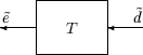
In this diagram, the input is on the right and the output is on the left for consistency with matrix and operator composition. This orientation is equivalent to the more traditional orientation with system input on the left and output on the right.
Assume that the dimensions of T are ne × nd. Let β > 0 be defined as the H∞ norm of T.
Now, consider a response, starting from an initial condition equal to 0. In this case, Parseval's theorem implies that
Moreover, there are specific disturbances d such that is arbitrarily close to β. As a result, ∥T∥∞ is referred to as the L2 (or RMS) gain of the system.
A sinusoidal, steady-state interpretation of ∥T∥∞ is also possible. For any frequency , any vector of amplitudes , and any vector of phases , with ∥a∥2 ≤ 1, define a time signal as
Applying this input to the system T results in a steady-state response of the form
The vector satisfies ∥b∥2 ≤ β. Moreover, β is the smallest number such that this condition is true for every ∥a∥2 ≤ 1, , and ϕ.
In this interpretation, the vectors of the sinusoidal magnitude responses are unweighted and measured in Euclidean norm. It is useful to characterize acceptable performance is in terms of the MIMO ∥·∥∞ (H∞) norm. However, a useful performance criterion must account for these system characteristics:
Relative magnitude of outside influences
Frequency dependence of signals
Relative importance of the magnitudes of regulated variables
Thus, to represent realistic multivariable performance objectives by a single MIMO ∥·∥∞ objective on a closed-loop transfer function, additional scalings are necessary. This approach requires collecting multiple objectives in one matrix, and using the norm of the matrix as the cost to optimize to achieve those objectives. To do so, you can apply frequency-dependent weighting functions to compute a weighted norm,
∥WLTWR∥.
This diagram illustrates the equivalent weighted system.
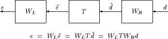
Here, the weighting function matrices WL and WR are frequency dependent to account for bandwidth constraints and spectral content of exogenous signals. WL and WR are diagonal, stable transfer function matrices, with diagonal entries denoted Li and Ri.
Typically, the diagonal structure is used because diagonal weights have a straightforward interpretation. Bounds on the quantity ∥WLTWR∥∞ imply bounds about the sinusoidal steady-state behavior of the signals and . Specifically, for sinusoidal signal , the steady-state relationship between , , and ∥WLTWR∥∞ is as follows. Denote the steady-state solution , where
Consider a sinusoidal input signal of the form
Further assume that also satisfies
For such an input signal , satisfies
if and only if ∥WLTWR∥∞ ≤ 1.
This analysis approximately implies that ∥WLTWR∥∞ ≤ 1 is satisfied if and only if for every fixed frequency , and all sinusoidal disturbances satisfying
the steady-state error components satisfy
This analysis shows how you can pick performance weights to reflect the desired frequency-dependent performance objective:
Choose WR to represent the relative magnitude of sinusoidal disturbances that might be present.
Choose 1/WL to represent the desired upper bound on the subsequent errors that are produced.
However, the weighted H∞ norm does not give element-by-element bounds on the components of based on element-by-element bounds on the components of . The precise bound the weighted H∞ norm gives is in terms of Euclidean norms of the components of and , weighted appropriately by WL(j) and WR(j). You can generalize this approach by applying distinct weights to components and , to capture a range of frequency-dependent performance objectives on a system. For more information, see H-Infinity Performance.