Create Target Registration Packages for C/C++ Test Execution on Targets
This example describes how to create a target registration package for running C/C++ tests authored with Polyspace® Test™ on a target. Here, the word target is used as an umbrella term for an embedded system with specific processor architecture, cross-compilation tools, and channels for communication with a host computer.
You can run both graphical and xUnit tests added to a Polyspace Platform project on a target. The steps to execute tests on targets are similar to those for executing tests on a host computer; however, you must perform a one-time setup to register your target in the Polyspace Platform user interface. This example describes how to create a target registration package for the one-time setup. The example uses a specific development board (STM32 Nucleo-144 board with STM32F767ZI MCU) as the target to illustrate the steps but you can easily generalize these steps to your development board.
For more information on using the target registration package for registering the target and running tests, see:
Overview
A target registration package primarily consists of a MATLAB® file for target registration and another for target unregistration. Other files in the package are referenced from the target registration and unregistration files.
To create a target package, follow these steps:
Generate C/C++ driver code to handle low-level I/O interactions with your target. Your target registration package will leverage the driver code for communication with the target. If you are already deploying your source code to a target, you may have generated these driver files.
Create a preferences file in JSON format to store target-related paths and other information. Others using your target package can simply modify this file to refer to paths on their machines without touching the rest of the package.
Create the outline of a target registration package. In particular, create a template target registration MATLAB file to read from the preferences file, and define and register a board and toolchain.
To complement the target registration, create a second MATLAB file for unregistering the previously registered board and toolchain.
Fill in the details of the MATLAB file for target registration. You might have to create additional supporting files along the way as needed.
This example walks through these steps for the STM32 Nucleo-144 development board.
Generate Driver Files
Before creating a target registration package, you must generate the driver files that handle all low-level I/O interactions with your target board. You can write the driver files for your board or generate them using software tools specific to your board. Once you have the driver files, save the root path to these files in a preferences file (see Create Preferences File).
The steps to generate the driver files vary depending on the target. If you are already deploying your source code to a target, you may have generated these driver files.
For the STM32 Nucleo-144 board, to generate these files, follow these steps1 :
Download the STM32CubeMX software.
In addition, you will also need these tools:
STM32CubeIDE, which comes with a GNU cross-compiler for Arm targets. You will provide the path to this compiler later.
STM32CubeProgrammer, which comes with a command-line tool to load your test executable on the board. You will provide the path to this tool later.
Open the STM32CubeMX tool. On the starting screen, select Start My project from ST Board > ACCESS TO BOARD SELECTOR.
Search for the STM32F7 series of boards, select the board NUCLEO-F767ZI in the search results and click Start Project.
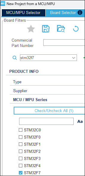
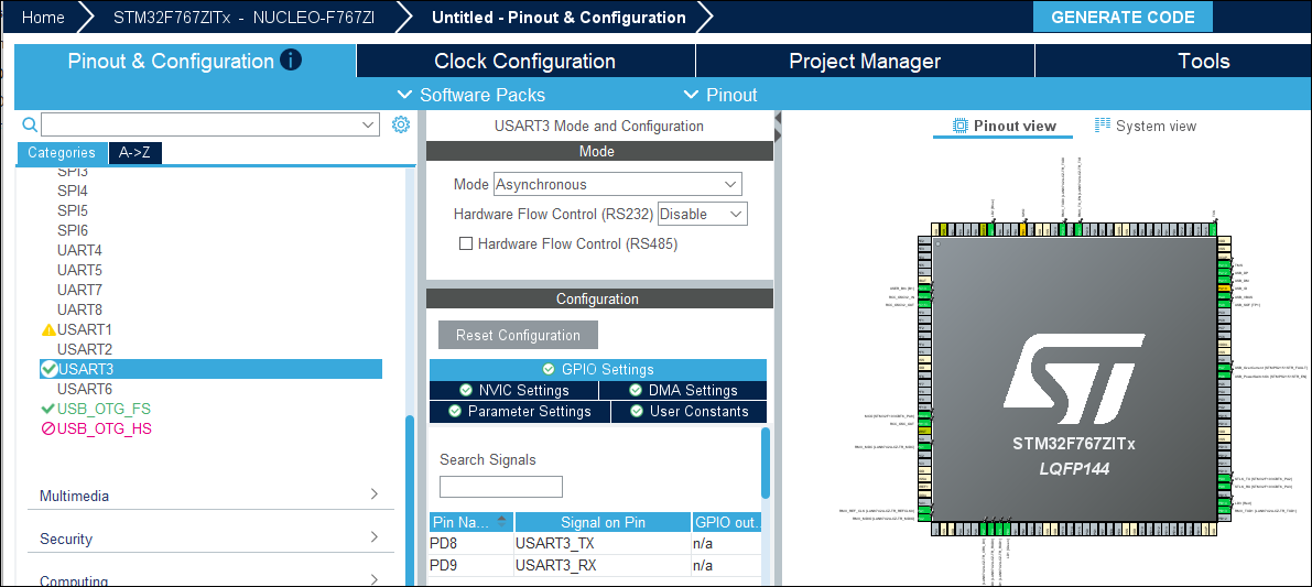
This creates a project and opens a layout of the board on a Pinout & Configuration tab.
On this tab, configure the type of communication your board will be using.
In this example, the USART communication interface will be used. To specify this communication interface:
In the Categories tree on the left, under the Connectivity section, select USART3. In the USART3 Mode and Configuration page on the right, select the
Asynchronousmode in the Mode dropdown. Then, in the Configuration section, configure this port as follows:Select the GPIO Settings tab. Note that the communications uses two pins, one for sending and another for receiving data.
Select the NVIC Settings tab. Make sure that the option USART3 global interrupt is selected. This is required because the communication between your host computer and the board will use global interrupts.
Select the DMA Settings tab. Click Add to add the
USART3_RXandUSART3_TXsettings.
In the Categories tree on the left, under the Timers section, select TIM1. Change Slave Mode to a setting other than
Disableand select a Trigger Source.
From the Pinout & Configuration tab, navigate to the Project Manager tab. In this example, you will not create a project but generate the driver files that a project typically uses for low-level I/O interaction.
Before generating driver code, specify these options to make sure that the generated driver files do not contain a
main()function:Project node – Enter a Project Name and Project Location. Select the option Do not generate the main() so that you can later specify your own
main()function via the target registration file. Also, note the location specified in Toolchain Folder Location. This is the location where your driver files will be stored (referred to asDriverPathlater). In addition, make sure that Toolchain / IDE is set toSTM32CubeIDEand Generate Under Root is not selected.Code Generator node – Select Generate peripheral initialization as a pair of ‘.c/.h’ files per peripheral. This option allows you to generate separate files with functions for your USART3 peripherals and call those functions from the
main()function that you will define using the target registration file.
Select Generate Code on the top right.
The driver files will be generated in the folder specified earlier for the setting Toolchain Folder Location.
Create Preferences File
To make sure that your target registration package is usable on multiple computers with minimal modifications, isolate information on paths specific to your computer into a separate preferences JSON file. Others using your target registration file can simply replace the paths in the JSON file without touching your target registration MATLAB code.
To create a preferences file for the STM32 Nucleo-144 board:
Copy the following JSON data (or equivalents for your STM32 Nucleo-144 board) into a file.
Here:{ "ProgrammerPath": "C:/Program Files/STMicroelectronics/STM32Cube/STM32CubeProgrammer/bin/STM32_Programmer_CLI.exe", "GnuARMPath": "C:/ST/STM32CubeIDE_1.16.1/STM32CubeIDE/plugins/com.st.stm32cube.ide.mcu.externaltools.gnu-tools-for-stm32.12.3.rel1.win32_1.0.200.202406191623/tools", "DriverPath": "C:/ProgramData/supportpackages/stm32/stm32f7xx_based/stm32f7xx_dpfp/boards/nucleo_f767zi", "ToolchainName": "GCC ARM Cortex M | STM32F767ZI", "BoardName": "STM32F767ZI Nucleo", "TargetConnectionName": "STM32 F767ZI - Host Connection", "COMPORT" : "COM3" }ProgrammerPathstores the file path to the STM32CubeProgrammer command-line interface (STM32_Programmer_CLI.exe). This interface is used to program (flash) the STM32 microcontroller.GnuARMPathstores the path to the GNU Arm toolchain binaries (compiler, assembler, linker, etc.) provided with STM32CubeIDE. This is used to build your embedded application for the STM32 board.DriverPathstores the path to the driver files you generated in the previous section.ToolchainNameandBoardNamestores the names to be used for the board and toolchain you will register. After target registration, these names appear for the optionsCompilation toolchain (Testing)andTarget board name (Testing).For the sake of brevity, the example preferences file stores only the board and toolchain name. You can store any constant (processor name, execution tool name, and so on) in the preferences file. Alternatively, you can store a single root name in the preferences file and create names by appending to the root name in your target registration MATLAB code.
COMPORTstores the serial communication port used to communicate with the board.
Create a folder
STM32Packageand save the preferences file astargetpreferences.json. In the next section, you will see how to read the preferences file.This is the beginning of your target package creation. You will save all subsequent files in this folder. As of now, your target package folder contains the following:
STM32Package/
├── targetpreferences.json
Create Target Registration Package
Create the outline of the target registration package:
A MATLAB function in a file
readJSONToStruct.mto read the JSON preferences.A subfolder
targetUtilitiesto store helper code, with a further subfoldersrcto store C code.A template MATLAB file
packageRegister.mfor target registration that calls the above function to read the preferences, adds the helper code subfolders to the MATLAB path, and outlines the steps required for target registration.A MATLAB file
packageUnregister.mthat unregisters the target.A
README.mdfile for notes.
At the end of this step, your target package folder will contain the following:
STM32Package/
├── targetpreferences.json
├── readJSONToStruct.m
├── packageRegister.m
├── packageUnregister.m
├── targetUtilities/
│   ├── src/
└── README.md
Reading Preferences File
To read the preferences JSON file, you can adopt one of the following approaches.
Write your own MATLAB function in the file
readJSONToStruct.mto read from a JSON file and return the JSON keys in a structure.Using this function allows you to access the JSON key values in MATLAB code using the returned structure. For instance, you can read the value of the JSON keyfunction jsonStruct = readJSONToStruct(jsonFullPath) arguments jsonFullPath (1,1) string end jsonStr = fileread(jsonFullPath); try jsonStruct = jsondecode(jsonStr); catch error('TargetJsonError'); end end
ProgrammerPathusing the syntax:prefs = readJSONToStruct("targetpreferences.json") prefs.ProgrammerPathDefine a MATLAB class that inherits from the class
pstest.target.TargetPreferences(available only with Polyspace Test). The class constructor takes a JSON file path as argument and reads the JSON into an object with the JSON keys as members. In this case, following MATLAB conventions, you will write the class definition in a fileSTM32F767ZI_Preferences.m.If you create an object of this class in MATLAB code:classdef STM32F767ZI_Preferences < pstest.target.TargetPreferences methods(Access=public) function this = STM32F767ZI_Preferences(jsonFullPath) arguments jsonFullPath (1,1) string end this@pstest.target.TargetPreferences(jsonFullPath); end end end
You can access the JSON key-values using the members of this object. For instance, in the above example, you can access the JSON keyprefs = STM32F767ZI_Preferences("targetpreferences.json");ProgrammerPathusingprefs.ProgrammerPath.
Creating Template File for Target Registration
Add the following template content for target registration to the file packageRegister.m. The template invokes the previously created function readJSONToStruct() to read the preferences file, adds all utility subfolders to the MATLAB path, and creates separate sections for the various characteristics of a target. In the next section, you will fill the various sections.
%% Read preferences file and create a preferences structure
currentFilePath = fileparts(mfilename('fullpath'));
addpath(currentFilePath);
jsonFullPath = fullfile(currentFilePath, 'targetpreferences.json');
prefs = readJSONToStruct(jsonFullPath);

%% Add targetUtilities folder to path
addpath("targetUtilities/");

%% Save path across all Polyspace sessions
if savepath
    warning('Error while saving path!');
end
rehash toolboxcache;

%% Create board

%% Create processor and set language implementation

%% Create toolchain and set processor as supported hardware

%% Specify how to start target hardware and associate with board

%% Create communication interface and associate with board

%% Create main function for execution on target and associate with board

%% Create data transfer protocol information and associate with board

%% (Optional) Create timer for profiling and associate with processor

%% Associate processor with board

%% Create a connection to board

%% Register connection to board and toolchain
Creating Target Unregistration File
Add the following content to the file packageUnregister.m to unregister the board and toolchain that would be created using the target registration file. When unregistering the board and toolchain, set the argument 'IncludeAssociations' to true so that any other object created as part of the board or toolchain also gets
removed.
% Read preferences file and create a preferences structure
currentFilePath = fileparts(mfilename('fullpath'));
addpath(currentFilePath);
jsonFullPath = fullfile(currentFilePath, 'targetpreferences.json');
prefs = readJSONToStruct(jsonFullPath);

% Remove toolchain definition
target.remove('Toolchain', prefs.ToolchainName, 'IncludeAssociations', true);

% Remove board definition
target.remove('TargetConnection', prefs.TargetConnectionName, 'IncludeAssociations', true);
Fill Details of Target Registration
You will now fill in the details of target registration. Each subsection below discusses how to fill a section of the target registration file (including creating necessary utility files), and shows the filled section for the STM32 Nucleo-144 board. The next section shows the complete target registration package, including the filled target registration file and all utility files.
Create Board
Create a target.Board object to represent the board.
%% Create board
board = target.create("Board", "Name", prefs.BoardName);
target.Board (Embedded Coder).Note that the variable prefs comes from the preferences file you created earlier.
Create Processor and Set Language Implementation
Create a target.Processor object to represent the processor. The processor encapsulates information such as name, manufacturer, timer, number of cores, and so on. For more information, see target.Processor (Embedded Coder).
The processor has a property LanguageImplementations, which is a target.LanguageImplementation object encapsulating details such as byte ordering and sizes of data types. Instead of setting the language implementation details explicitly, you can use target.get (Embedded Coder) to automatically populate the language implementation
details. For more information, see target.LanguageImplementation (Embedded Coder).
%% Create processor and set language implementation
processor = target.create("Processor", ...
    "Name", "STM32F767ZI", ...
    "Manufacturer", 'ST');
processor.LanguageImplementations = target.get("LanguageImplementation","GNU GCC ARM 32-bit");
availableLanguageImplementations = target.get("LanguageImplementation")Create Toolchain and Set Processor as Supported Hardware
Create a target.Toolchain object to represent the toolchain for building C/C++ code. You can specify a toolchain in one of the following ways:
Using a CMake-style toolchain specification, which describes a compiler, linker, and so on, in CMake language.
Explicitly specifying paths to your compiler, linker, and so on. In this case, a makefile will be created for building code.
This example explicitly specifies paths to compilers and other toolchain binaries. However, instead of explicitly specifying every detail of the compiler binaries, it uses a shorthand notation available for GNU®-family toolchains.
For GNU-family toolchains, where the compile command is a variant of gcc such as arm-none-eabi-gcc and accepts gcc options, you can use the following shorthand. Instead of a creating an empty toolchain and specifying all toolchain properties:
toolchain = target.create('Toolchain', ...
     'Name', 'GCC ARM Cortex M | STM32F767ZI')
% Specify full set of properties %
toolchain = target.create('Toolchain', ...
     'Name', 'GCC ARM Cortex M | STM32F767ZI', ...
     'Family', 'GNU', ...
     'ToolPrefix', 'arm-none-eabi-', ...
     'MakeTool', 'gmake')
% Specify minimal set of properties %
target.Toolchain (Embedded Coder).The software development tools for the STM32 Nucleo-144 board uses a GNU-family toolchain with the arm-none-eabi- toolchain prefix. Use the above shorthand to create a preconfigured toolchain and specify only the following additional information:
Path to folder containing compiler and other binaries (using the
SytemPathsargument).Additional compiler and linker flags (using the
CompilerFlagsandLinkerFlagsarguments).
Finally, add the previously created processor as a supported hardware for the toolchain.
%% Create toolchain and set processor as supported hardware
compilerLinkerFlags = [
    "-mcpu=cortex-m7", ...
    "-mthumb", ...
    "-mfpu=fpv5-sp-d16", ...
    "-mfloat-abi=hard"
];

linkerFlag = "-T " + prefs.DriverPath + "/STM32CubeIDE/STM32F767ZITX_FLASH.ld";
toolchain = target.create('Toolchain', ...
    'Family', 'GNU', ...
    'Name', prefs.ToolchainName, ...
    'ToolPrefix', 'arm-none-eabi-', ...
    'MakeTool', 'gmake', ...
    'SystemPaths', [prefs.GnuARMPath '/bin'], ...
    'CompilerFlags', [ ...
        compilerLinkerFlags, ...
        "-ffunction-sections", ...
        "-fdata-sections", ...
        "-Wall" ...
    ], ...
    'LinkerFlags', [ ...
        compilerLinkerFlags, ...
        linkerFlag ...
    ] ...
);

toolchain.SupportedHardware = target.create( ...
    'HardwareComponentSupport', ...
    'Component', processor ...
);
Note that the variable prefs comes from the preferences file you created earlier.
Instead of writing the toolchain registration code by hand, you can also generate the code using a Toolchain app. For more information, see Toolchain.
Specify How to Start Target Hardware and Associate With Board
Create a target.Command object to specify a command that executes applications on the STM32 Nucleo-144 board. Then, specify this command as an execution tool associated with the board.
%% Specify how to start target hardware and associate with board

startCommand = target.create('Command');
startCommand.String = prefs.ProgrammerPath;
startCommand.Arguments = {'--connect' ...
    'port=swd'...
    '--erase' ...
    'all' ...
    '--download'...
    '$(EXE)' ...
    '--go'};


executionTool = target.create( ...
    "SystemCommandExecutionTool", ...
    "Name", "STLink V2 VCP  - Target Process Execution", ...
    "StartCommand", startCommand ...
);

board.Tools.ExecutionTools = executionTool;
$(EXE) to denote the application executable. If the executable to download and run is named timesTwo.elf, the above target.Command object effectively implements this system command:STM32_Programmer_CLI.exe --connect port=swd --erase all --download timesTwo.elf --goAlternate Approach for Defining Execution Tool. The above code snippet is the simplest way to add start (or stop) commands that load applications on your board. In the more general case, for instance, if you use an emulator or debugger, you might need to call separate commands at the start – one command that starts the emulator and a separate one that starts the actual application. In this case, create a class that inherits from the target.ExecutionTool or target.DebugIOTool class, and
implement methods such as startApplication, stopApplication, and so on. For more information, see target.ExecutionTool (Embedded Coder) or target.DebugIOTool (Embedded Coder).
For instance, to implement the same start command as above using the target.ExecutionTool class:
In a new file
STM32F767ZI_ExecutionTool.m, create a classSTM32F767ZI_ExecutionToolthat inherits fromtarget.ExecutionTooland implement thestartApplicationmethod of the class. In the implementation below, the method calls the sameSTM32_Programmer_CLI.exesystem command as earlier and in addition, displays some messages.classdef STM32F767ZI_ExecutionTool < target.ExecutionTool methods % Start executing the application on the target. function errFlag = startApplication(this) binFullPath = char(this.Application); currentFilePath = fileparts(mfilename('fullpath')); parentPath = currentFilePath(1:end-length('targetUtilities')-1); jsonFullPath = fullfile(parentPath, 'targetpreferences.json'); prefs = readJSONToStruct(jsonFullPath); programmerPath = prefs.ProgrammerPath; disp(programmerPath); [~, name, ext] = fileparts(binFullPath); disp(['Programming ' name ext]); cwd = [ ... '"', char(programmerPath), ... '" --connect port=swd --erase all --download "', ... binFullPath, ... '" --go' ... ]; [status, cmdout] = system(cwd); if status ~= 0 error(cmdout); errFlag = true; else disp('Programming successfull !'); errFlag = false; end end end end
Save the MATLAB file
STM32F767ZI_ExecutionTool.min thetargetUtilitiesfolder.Your folder structure looks like this:
STM32Package/
├── targetpreferences.json
├── readJSONToStruct.m
├── packageRegister.m
├── packageUnregister.m
├── targetUtilities/
│   ├── STM32F767ZI_ExecutionTool.m
│   ├── src/
└── README.md
In your target registration file
packageRegister.m, create atarget.ExecutionServiceobject, which allows you to use the MATLAB class you implemented to start the application on the board.%% Specify how to start target hardware and associate with board % Create a MATLAB build dependency on the class derived from target.ExecutionTool class buildDeps = target.create("MATLABDependencies", "Classes", "STM32F767ZI_ExecutionTool"); % Create an execution service that uses an API % That is obtained from the MATLAB build dependency api = target.get("API", "ExecutionTool"); executionServiceAPI = target.create("APIImplementation", ... "Name", "STM32F767ZI - Execution Service Implementation", ... "API", api, ... "BuildDependencies", buildDeps); executionService = target.create("ExecutionService", ... "Name", "STM32F767ZI - Target Process Execution", ... "APIImplementation", executionServiceAPI); % Associate the execution service with the board board.Tools.ExecutionTools = executionService;
Create Communication Interface and Associate with Board
Create a target.CommunicationsInterface object to send data to and receive data from the board. The object has two properties:
Channel: This property states the name of the standard to be used for communication. In this example, you specify that the communication happens using an RS-232 channel.APIImplementations: This property implements the actual details of communication using the driver files you generated earlier.In this example, you specified that the communication with the board happens using USART peripherals and then generated driver code for this communication. If you communicated with your board outside the Polyspace context, for instance, using an STM32CubeIDE project, you would be using the functions from the driver code for communication, for instance,
HAL_UART_Transmit()for sending data andHAL_UART_Receive()for receiving data. For targets registered using the target framework API, the same communication is handled using thertiostreamC API. For instance, this API uses the functionrtIOStreamSend()for sending data andrtIOStreamRecv()for receiving data. To leverage the generated driver code, you have to create custom implementations of the functions from thertiostreamAPI that call functions from the generated driver code.
To create and add a custom implementation of the rtiostream API, follow these steps.
Implement these functions of the
rtiostreamAPI:rtIOStreamOpen(Embedded Coder)rtIOStreamSend(Embedded Coder)rtIOStreamRecv(Embedded Coder)rtIOStreamClose(Embedded Coder)
For the STM32 Nucleo-144 board, create the following header and source file containing implementations of the
rtiostreamAPI:customRtiostream.h:#ifndef STM32F767ZI #define STM32F767ZI #include <stddef.h> #define RTIOSTREAM_ERROR (-1) #define RTIOSTREAM_NO_ERROR (0) /* Note: if the functions declared in this file should be compiled into a shared * library (e.g. a .dll file on Windows), you must ensure that the functions are * externally visible. The procedure to achieve this depends on the compiler and * linker you are using. For example, on Windows, you may need to provide an * exports definition .def file that lists all of the functions to be * exported; see ./rtiostream/rtiostream_pc.def for a suitable .def file. */ extern int rtIOStreamOpen( int argc, void * argv[] ); extern int rtIOStreamSend( int streamID, const void * src, size_t size, size_t * sizeSent ); extern int rtIOStreamRecv( int streamID, void * dst, size_t size, size_t * sizeRecvd ); extern int rtIOStreamClose( int streamID ); #endif /* #ifndef STM32F767ZI_SERIAL */customRtiostream.c:#include "customRtiostream.h" #include "STM32F767ZI_board.h" #include "stm32f7xx_hal.h" #include "stm32f7xx_hal_uart.h" extern UART_HandleTypeDef huart3; int rtIOStreamOpen(int argc, void * argv[]) { (void)argc; (void)argv; return RTIOSTREAM_NO_ERROR; } int rtIOStreamSend(int streamID, const void * src, size_t size,size_t* sizeSent) { (void)streamID; if (HAL_OK == HAL_UART_Transmit(&huart3, src, size, HAL_MAX_DELAY)) { *sizeSent = size; return RTIOSTREAM_NO_ERROR; } else { *sizeSent = (size - huart3.TxXferCount); return RTIOSTREAM_ERROR; } } int rtIOStreamRecv(int streamID, void * dst, size_t size, size_t* sizeRecvd) { (void)streamID; if (HAL_OK == HAL_UART_Receive(&huart3, dst, size, HAL_MAX_DELAY)) { *sizeRecvd = size; return RTIOSTREAM_NO_ERROR; } else { *sizeRecvd = (size - huart3.RxXferCount); return RTIOSTREAM_ERROR; } } int rtIOStreamClose(int streamID) { (void)streamID; return RTIOSTREAM_NO_ERROR; }
Save the header and source file in the
targetUtilities/srcsubfolder. At the end of this step, the target package looks like this:STM32Package/ ├── targetpreferences.json ├── readJSONToStruct.m ├── packageRegister.m ├── packageUnregister.m ├── targetUtilities/ │ ├── STM32F767ZI_ExecutionTool.m #Optional │ ├── src/ │ │ ├── customRtiostream.h │ │ ├── customRtiostream.c └── README.md
In your target registration file
packageRegister.m, create atarget.CommunicationsInterfaceobject that refers to the above custom implementation of thertiostreamC API.%% Create communication interface and associate with board % Create communication interface comms = target.create( ... "CommunicationInterface", ... "Name", "STLink V2 VCP - Communication Interface" ... ); comms.Channel = "RS232Channel"; comms.APIImplementations = target.create( ... "APIImplementation", ... "Name", "STLink V2 VCP - APIImplementation" ... ); % Specify that you will be using the rtiostream API for communication comms.APIImplementations.API = target.get( ... 'API', 'rtiostream' ... ); % Specify the location of your custom rtiostream implementation as a build dependency. % Also, specify the location of the driver includes baseSoftDir = [currentFilePath, '/targetUtilities/src']; comms.APIImplementations.BuildDependencies = target.create( ... "BuildDependencies" ... ); comms.APIImplementations.BuildDependencies.SourceFiles = [ ... baseSoftDir, '/customRtiostream.c' ... ]; comms.APIImplementations.BuildDependencies.IncludeFiles = [ ... baseSoftDir, '/customRtiostream.h' ... ]; comms.APIImplementations.BuildDependencies.IncludePaths = [ ... prefs.DriverPath, '/Drivers/STM32F7xx_HAL_Driver/Inc' ... ]; % Finally, associate the communication interface with the board board.CommunicationInterfaces = comms;
For more information, see target.CommunicationInterface (Embedded Coder).
Create Main Function for Execution on Target and Associate With Board
Create a target.MainFunction object that defines the entry point to your application. When generating driver files earlier, you specified that a main() function must not be generated. The reason was that building using the target framework API itself involves generation of an intermediate main function. In this section of target registration, you specify the ingredients of the generated main using the
target.MainFunction. For more information, see target.MainFunction (Embedded Coder).
For the STM32 Nucleo-144 example, your main() function will initialize the board using functions in the generated driver files. You will write a custom initialization function in C that calls low-level initialization functions in the generated driver files, then refer to this custom initialization function in your target registration file.
Create the following header and source file that declares and defines a function
initSTM32F767ZI(), which calls low-level initialization functions. In the header, make sure to include all the appropriate driver files:STM32F767ZI_board.h:#ifndef STM32F767ZI_board #define STM32F767ZI_board #include "main.h" #include "dma.h" #include "tim.h" #include "usart.h" #include "gpio.h" #include "stm32f7xx_hal.h" extern void initSTM32F767ZI(void); #endif /* STM32F746G_DISCOVERY_BOARD */STM32F767ZI_board.c:#include "STM32F767ZI_board.h" extern UART_HandleTypeDef huart3; //defined in usart.c extern TIM_HandleTypeDef htim1; //defined in tim.c void initSTM32F767ZI(void) //Wraper function called in Initialization phase { MX_GPIO_Init(); //GPIO Initialization defined in gpio.c MX_DMA_Init(); //DMA Initialization defined in dma.c // Configure the Timer MX_TIM1_Init(); //TIM Initialization defined in tim.c HAL_TIM_Base_MspInit(&htim1); //Peripherical initialization defined in tim.c HAL_TIM_Base_Start(&htim1); //Start timer // Configure the required peripherals MX_USART3_UART_Init(); //USART3 Initialization defined in usart.c HAL_UART_MspInit(&huart3); //Peripherical initialization defined in usart.c }
Save the header and source file in the
targetUtilities/srcsubfolder. At the end of this step, the target package looks like this:STM32Package/ ├── targetpreferences.json ├── readJSONToStruct.m ├── packageRegister.m ├── packageUnregister.m ├── targetUtilities/ │ ├── STM32F767ZI_ExecutionTool.m #Optional │ ├── src/ │ │ ├── customRtiostream.h │ │ ├── customRtiostream.c │ │ ├── STM32F767ZI_board.h │ │ ├── STM32F767ZI_board.c └── README.md
In your target registration package
packageRegister.m, create atarget.MainFunctionobject. In theInitializationCodeproperty of this object, call the initialization function defined in the previous step.%% Create main function for execution on target and associate with board mainFunction = target.create("MainFunction", "Name", "Test Main"); % Add the include file 'STM32F767ZI_board.h' so that it gets included in the generated main mainFunction.IncludeFiles = {[baseSoftDir,'/STM32F767ZI_board.h']}; % Add code that directly goes into the body of the generated main % In this example, you can just add a call to the previously defined initialization function mainFunction.InitializationCode = sprintf('initSTM32F767ZI();\n'); % Add paths to all generated driver files % The driver files contain definitions of low-level functions to be used during build % Also add necessary include paths and defines driverPath = prefs.DriverPath; mainFunction.BuildDependencies.SourceFiles = { ... [driverPath, '/STM32CubeIDE/Application/User/Startup/startup_stm32f767zitx.s'], ... [baseSoftDir, '/STM32F767ZI_board.c'] ... [driverPath, '/Core/Src/gpio.c']... [driverPath, '/Core/Src/usart.c']... [driverPath, '/Core/Src/dma.c']... [driverPath, '/Core/Src/tim.c']... [driverPath, '/Core/Src/main.c']... [driverPath, '/STM32CubeIDE/Application/User/Core/syscalls.c'] ... [driverPath, '/STM32CubeIDE/Application/User/Core/sysmem.c'] ... [driverPath, '/Core/Src/system_stm32f7xx.c'] ... [driverPath, '/Core/Src/stm32f7xx_it.c'] ... [driverPath, '/Drivers/STM32F7xx_HAL_Driver/Src/stm32f7xx_hal.c'] ... [driverPath, '/Drivers/STM32F7xx_HAL_Driver/Src/stm32f7xx_hal_cortex.c'] ... [driverPath, '/Drivers/STM32F7xx_HAL_Driver/Src/stm32f7xx_hal_dma.c'] ... [driverPath, '/Drivers/STM32F7xx_HAL_Driver/Src/stm32f7xx_hal_exti.c'] ... [driverPath, '/Drivers/STM32F7xx_HAL_Driver/Src/stm32f7xx_hal_flash.c'] ... [driverPath, '/Drivers/STM32F7xx_HAL_Driver/Src/stm32f7xx_hal_flash_ex.c'] ... [driverPath, '/Drivers/STM32F7xx_HAL_Driver/Src/stm32f7xx_hal_gpio.c'] ... [driverPath, '/Drivers/STM32F7xx_HAL_Driver/Src/stm32f7xx_hal_pwr.c'] ... [driverPath, '/Drivers/STM32F7xx_HAL_Driver/Src/stm32f7xx_hal_rcc.c'] ... [driverPath, '/Drivers/STM32F7xx_HAL_Driver/Src/stm32f7xx_hal_rcc_ex.c'] ... [driverPath, '/Drivers/STM32F7xx_HAL_Driver/Src/stm32f7xx_hal_tim.c'] ... [driverPath, '/Drivers/STM32F7xx_HAL_Driver/Src/stm32f7xx_hal_tim_ex.c'] ... [driverPath, '/Drivers/STM32F7xx_HAL_Driver/Src/stm32f7xx_hal_uart.c'] ... [driverPath, '/Drivers/STM32F7xx_HAL_Driver/Src/stm32f7xx_hal_pwr_ex.c'] }; mainFunction.BuildDependencies.IncludePaths = ... { [driverPath, '/Drivers/STM32F7xx_HAL_Driver/Inc'] ... [driverPath, '/Drivers/CMSIS/Device/ST/STM32F7xx/Include'], ... [driverPath, '/Drivers/CMSIS/Include'],... [driverPath, '/Core/Inc'],... baseSoftDir }; mainFunction.BuildDependencies.Defines = ... { 'STM32F767xx', 'USE_HAL_DRIVER', 'USE_FULL_LL_DRIVER' }; % Associate main function with board board.MainFunctions = mainFunction;
Create Data Transfer Protocol Information and Associate With Board
Create a target.PILProtocol object to specify additional information around data transfer such as buffer sizes and timeouts for sending or receiving data.
%% Create data transfer protocol information and associate with board pilProtocol = target.create("PILProtocol"); pilProtocol.Name = "STM32F767ZI - PIL Protocol"; pilProtocol.ReceiveTimeout = 60; pilProtocol.OpenTimeout = 60; pilProtocol.SendBufferSize = 1024; pilProtocol.ReceiveBufferSize = 1024; board.CommunicationProtocolStacks = pilProtocol;
For more information, see target.PILProtocol (Embedded Coder).
(Optional) Create Timer for Profiling and Associate With Processor
If you want to perform execution time calculation for your target, create a target.Timer object to specify the timer function to be used for calculation.
For the STM32 Nucleo-144 example, follow these steps to specify a timer function:
In the previously created header file
STM32F767ZI_board.h, add the following function declaration:extern uint32_t getTimerCounter(void);Add the definition of the above function to the previously created source file
STM32F767ZI_board.c:The function uses the builtin macro#include "STM32F767ZI_board.h" uint32_t getTimerCounter(void) { return __HAL_TIM_GET_COUNTER(&htim1); }__HAL_TIM_GET_COUNTERto get the current counter value of a timer.In your target registration file
packageRegister.m, create atarget.Timerobject that refers to the timer function defined in the previous step.%% Create timer for profiling and associate with processor timer = target.create("Timer", "Name", "STM32 F767ZI Timer", ... "FunctionName","getTimerCounter", ... "FunctionReturnType","uint32", ... "IncludeFiles",{'STM32F767ZI_board.h'}, ... "FunctionLanguage","C"); target.add(timer, "UserInstall", true); processor.Timers = timer;
For more information, see target.Timer (Embedded Coder).
Create Processor With Board
Connect the previously created target.Processor object to the previously created target.Board object:
%% Associate processor with board
board.Processors = processor;Create Connection to Board
Create a target.TargetConnection object to create a connection to the board from your host computer.
%% Create a connection to board connection = target.create("TargetConnection"); connection.Name = prefs.TargetConnectionName; % Specify the communication channel used earlier when defining the communication interface connection.CommunicationChannel = target.create("RS232Channel"); connection.CommunicationChannel.Name = "STLink V2 VCP - RS232Channel"; % Specify the required Baud Rate and COM Port connection.CommunicationChannel.BaudRate = 115200; connection.ConnectionProperties = target.create("Port","PortNumber",prefs.COMPORT); % Attach the board to the connection object connection.Target = board;
For more information, see target.TargetConnection (Embedded Coder).
Register Connection to Board and Toolchain
Add the previously created board connection and toolchain to the list of registered targets.
%% Register connection to board and toolchain % Add the connection to the database of registered targets target.add(connection, "UserInstall", true); % Add the toolchain to the database of registered toolchains target.add(toolchain, "UserInstall", true);
For more information, see target.add (Embedded Coder).
Summary
Your final target registration package consists of the following files.
STM32Package/
├── targetpreferences.json
├── readJSONToStruct.m
├── packageRegister.m
├── packageUnregister.m
├── targetUtilities/
│   ├── STM32F767ZI_ExecutionTool.m   #Optional
│   ├── src/
│   │   ├── customRtiostream.h
│   │   ├── customRtiostream.c
│   │   ├── STM32F767ZI_board.h
│   │   ├── STM32F767ZI_board.c
└── README.md
The completed package registration file packageRegister.m contains the following code. You can use this package registration file to register the board for use with Polyspace
Test. Once registered, you can:
Build and run C/C++ code and tests on the board. For building and running in the Polyspace Platform user interface, see Run C/C++ Tests on Target in Polyspace Platform User Interface. For building and running at the command line, see Automate C/C++ Test Execution on Targets Using Polyspace Platform Projects.
Validate the target registration package without creating a project. For validating in the Polyspace Platform user interface, see Run C/C++ Tests on Target in Polyspace Platform User Interface. For validating at the command line, see
polyspace-test -check-target-package. Validation at the command line can provide more diagnostic information.
See Also
Topics
1 The files referred to in this example are the copyrighted property of STMicroelectronics®. Their names are used here for informational purposes only.