Distributed Beamforming Using 1-Bit Feedback
This example shows how to synchronize the frequency and phase of distributed nodes to enable beamforming. The nodes are synchronized using Gaussian Minimum Shift Keying (GMSK) modulated feedback signals from the base station that is receiving the beamformed continuous wave (CW) signals. The phases of the nodes are synchronized using a 1-bit feedback. The root mean square (RMS) amplitude of the beamformed signals is evaluated.
Introduction
Small distributed wireless systems have recently attracted researchers due to their ability to transmit and/or receive similar or higher power compared to bulky platform-centric systems. Distributed wireless systems can be formed by multiple user equipment (UE), CubeSats/satellites, and/or stationary antennas. Once the electric states of distributed wireless systems are synchronized, beamforming on either transmit or receive is possible leading to high power improvements. The main parameters that need to be synchronized are the frequency, phase, and time. Node synchronization can be achieved using a multitude of architectures; in particular, one can synchronize the beamforming nodes using only 1-bit feedback from the receiver, which can be referred to as base station.
In this example, coherent signals are transmitted towards a base station from four nodes. The synchronization is performed over multiple iterations, where the beamformed signals are continuously evaluated to generate the desired feedback to the nodes. The effects of phase noise and frequency random walks of the oscillators are taken into account. The frequency of every oscillator is considered stable for the duration of a given iteration. The base station and all the beamforming nodes are assumed to be time-aligned.

Initialization
First, the parameters that are used in this example are initialized. The transmit carrier frequency of the base station and the receive carrier frequency of the beamforming nodes are both set to 964 MHz. These two carrier frequencies have to be equal so that the beamforming nodes can receive the synchronization signals from the base station. On the other hand, the transmit carrier frequency of the beamforming nodes and the receive carrier frequency of the base station are both set to 892 MHz. Two different bands were selected so that we can simulate the case where both synchronization and beamforming are performed simultaneously. The packet size of the GMSK synchronization signals is set to 150 bits. The baseband frequency of the beamformed CW signals is set to 1 kHz; and the sampling rate for the transmitted and received signals is set to 20 kHz.
rng('default');
nodeNbr = 4;            % The number of beamforming nodes
fcBsTx  = 964e6;        % Base station transmit (Tx) carrier frequency (Hz)
fcBnTx  = 892e6;        % Beamforming nodes Tx carrier frequency (Hz)
fcBsRx  = fcBnTx;       % Base station receive (Rx) carrier frequency (Hz)
fcBnRx  = fcBsTx;       % Beamforming nodes RX carrier frequency (Hz)
fbB     = 1e3;          % Baseband frequency of the beamformed signals (Hz)
fs      = 20e3;         % Sample rate (Hz)
packetSize       = 175; % GMSK packet size
samplesPerSymbol = 2;   % Samples per symbol for the GMSK signals
cwSamples        = 300; % Sample size of the CW signals
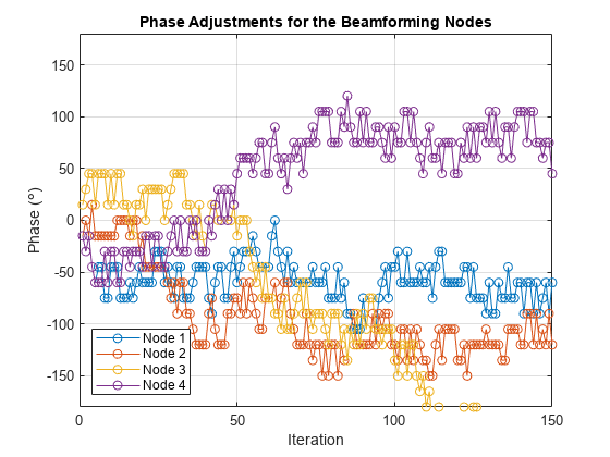
The phase correction for every node was performed by adding a random value on every iteration from a set of options using a uniform distribution. If the randomly added phases for all the nodes improved the RMS amplitude of the beamformed signals, the additional phases are retained, otherwise the added phases are reverted. The base station transmits the feedback about the change of the RMS amplitude to the beamforming nodes using a 1-bit feedback.
iterNbr       = 150;                   % The total number of iterations
rmsSigBBsRx   = zeros(iterNbr,1);      % RMS amplitude of beamformed signals
deltaRMSBs    = 0;                     % RMS amplitude change of the beamformed signals
bitFeedbackRX = ones(1,nodeNbr);       % Received bit feedback
deltaPhaseOptions = deg2rad([-15,15]); % Options for phase adjustments (rad)
To model the frequency drift at receive for the beamforming nodes relatively to the frequency of the base station transmitter, which is caused by the imperfections of real voltage-controlled oscillators (VCOs), every beamforming node is initialized with a random frequency offset. This frequency offset will be later bounded between +/- 2 kHz.
fOffsetBnRx      = zeros(iterNbr,nodeNbr);
fOffsetBnRx(1,:) = 404*randn(1,nodeNbr); % Frequency offset at the beamforming node Rx (Hz)
fOffsetBnRxMax   = 1e3;  % Maximum allowed frequency offset at the beamforming node Rx (Hz)
fOffsetBnRxMin   = -1e3; % Minimum allowed frequency offset at beamforming node Rx (Hz)
The frequency offset on receive is going to be estimated. Based on the estimated frequency offset, a certain frequency correction will be applied at receive and transmit. Similar to the frequency offset, every node has a phase offset relative to the phase of the base station. The phase offset changes based on the frequency offset between the nodes. Even when the nodes are frequency synchronized, a small frequency offset will exist. Thus, there will always be a random phase shift at the beginning of every iteration.
pfoGMSK = comm.PhaseFrequencyOffset(SampleRate=fs,...
    FrequencyOffsetSource="Input port");
pfoCW   = clone(pfoGMSK);
phaseOffsetBnTx = -pi + (2*pi)*rand(1,nodeNbr); % Initial phase offset (rad)

[fOffsetEstBnRx,fCorrBnRx,fCorrBnTx,fcBnTxAct,phaseCurrentCorrBnTx,...
    phaseTotalCorrBnTx,phaseBnTxAct,phaseOffsetActBnRx,phaseOffsetActBnTx,...
    phaseOffsetEstBnTx,phaseOffsetEstBnRx] = helperVarInitialization(iterNbr,nodeNbr);
Phase noise objects for the VCOs are initialized to be the same at transmit and receive regardless of whether the signal is upconverted or downconverted. The phase noise is only modeled for the beamforming nodes since the phase noise of the base station should not affect the RMS amplitude of the beamformed signals.
phNzLevel    = [-100,-140,-155];    % Phase Noise (dBc/Hz)
phNzFreqOff  = [1e2,1e3,9.5e3];     % Phase Offset (Hz)
pnoiseUpBS   = comm.PhaseNoise(Level=phNzLevel, ...
    FrequencyOffset=phNzFreqOff, SampleRate=fs);
pnoiseDownBS = comm.PhaseNoise(Level=phNzLevel, ...
    FrequencyOffset=phNzFreqOff, SampleRate=fs);
pnoiseUpBN   = clone(pnoiseUpBS);
pnoiseDownBN = clone(pnoiseDownBS);
The transmit and receive objects of the GMSK and Sinusoidal wave objects are initialized.
gmskModulatorData = comm.GMSKModulator('BitInput',true,'PulseLength',1,...
    'SamplesPerSymbol',samplesPerSymbol,'InitialPhaseOffset',0);
gmskDemodulator   = comm.GMSKDemodulator('BitOutput',false,'PulseLength',1,...
    'SamplesPerSymbol',samplesPerSymbol,'InitialPhaseOffset',0);
sine = dsp.SineWave('Frequency',fbB,'SampleRate',fs,...
    'PhaseOffset',0,'ComplexOutput',true,'SamplesPerFrame',cwSamples);
In addition, the header portion of the GMSK signal is initialized.
bitHeader           = repmat([1;1;1;1;1;0;0;1;1;0;1;0;1],[2,1]); % Packet header bits
gmskModulatorHeader = clone(gmskModulatorData);
headerSignal        = gmskModulatorHeader(bitHeader); % Signal portion of the header
The peak transmit power of the base station is set to 1 W with a gain of 40 dB, while the peak transmit power of the beamforming nodes is set to 0.1 W with a gain of 10 dB. The receivers were also modeled to have different gain and loss factors.
transmitterBs = phased.Transmitter('PeakPower',1,'Gain',40);
transmitterBn = phased.Transmitter('PeakPower',0.1,'Gain',10);
receiverBs    = phased.ReceiverPreamp('NoiseFigure',4, ...
    'SampleRate',fs,'NoiseComplexity','Real','LossFactor',10,'Gain',40);
receiverBn    = phased.ReceiverPreamp('NoiseFigure',7, ...
    'SampleRate',fs,'NoiseComplexity','Real','LossFactor',3,'Gain',10);
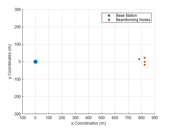
The location and velocity of all the nodes are selected.
posBs      = zeros(3,1);         % Position of the base station (m)
posBn      = repmat([0;0;0],[1,nodeNbr]); % Position of the beamforming nodes (m)
posBn(1,:) = 775 + 50.*rand(1,nodeNbr);
posBn(2,:) = -25 + 50.*rand(1,nodeNbr);
velBs      = zeros(3,1);         % Velocity of the base station (m/s)
velBn      = zeros(3,nodeNbr);   % Velocity of the beamforming nodes (m/s)

[~,angAzElBs] = rangeangle(posBn,posBs);
[~,angAzElBn] = rangeangle(posBs,posBn);

figure
scatter(posBs(1),posBs(2),100,'filled')
hold on; grid on
scatter(posBn(1,:),posBn(2,:),25,'filled')
xlim([-100,900]); ylim([-300,300])
legend('Base Station','Beamforming Nodes')
xlabel ('x Coordinates (m)'); ylabel ('y Coordinates (m)')
The antennas of the base station were selected as uniform rectangular arrays, while the antennas of the beamforming nodes were selected as isotropic antenna elements.
antennaBn    = phased.IsotropicAntennaElement;
AntSpac      = physconst('LightSpeed')/fcBsTx/2;
antennaBs    = phased.URA('Size',[3 3],'ElementSpacing',AntSpac);

radiatorBs   = phased.Radiator('Sensor',antennaBs,...
    'OperatingFrequency',fcBsTx,'CombineRadiatedSignals',true);
radiatorBn   = phased.Radiator('Sensor',antennaBn,...
    'OperatingFrequency',fcBnTx);

collectorBn  = phased.WidebandCollector('Sensor',antennaBn,...
    'SampleRate',fs,'CarrierFrequency',fcBnRx);
collectorBs  = phased.WidebandCollector('Sensor',antennaBs,...
    'SampleRate',fs,'CarrierFrequency',fcBsRx);

beamformerBs = phased.PhaseShiftBeamformer('SensorArray',antennaBs,...
    'OperatingFrequency',fcBsRx,'Direction',[0;0]);

henvBsTx     = phased.FreeSpace('SampleRate',fs,...
    'OperatingFrequency',fcBsTx);
henvBnTx     = phased.FreeSpace('SampleRate',fs,...
    'OperatingFrequency',fcBnTx);
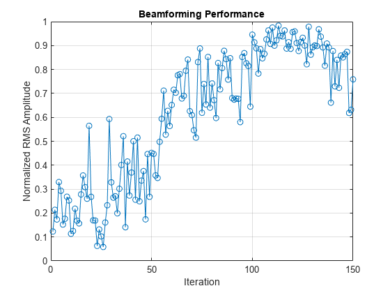
Beamforming performance is evaluated over 150 iterations.
for iter = 1:iterNbrSynchronization of the Beamforming Nodes
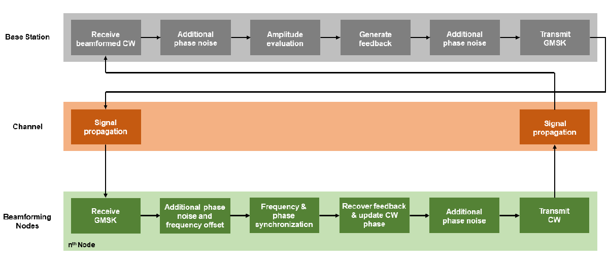
Beamforming is enabled by first synchronizing the frequencies and phases of the 4 beamforming nodes. The nodes are assumed to be time-aligned. The beamforming nodes synchronize themselves based on the feedback signal transmitted from the base station. The feedback is represented by a GMSK signal with a known header, 1-bit feedback, and a payload with random bits. The beamforming nodes synchronize their frequencies to the center frequency of the received feedback signal. The 1-bit feedback is used to decide whether the last update to the phases increased the beamformed power or decreased it. If there was an improvement in the received power at the base station, the last phase updates to the signals of the beamforming nodes are kept; otherwise they are reversed. A block diagram summarizing the main steps for the process of synchronization and beamforming is shown below. Additional details about the beamforming process are found in the next section.
The signal packet of the synchronization signals transmitted from the base station contains header bits, a feedback bit, and a payload that contains random bits.
bitFeedback = deltaRMSBs >= 0;
bitRemainingPayload = randi([0 1],packetSize - length([bitHeader;bitFeedback]),1);
dataBsTx    = [bitHeader;bitFeedback;bitRemainingPayload];
The GMSK signal is generated for the desired packet and additional phase noise from the VCO of the base station transmitter is added. Afterwards, the signal is transmitted.
gmskBsTx = gmskModulatorData(dataBsTx);
gmskBsTx = pnoiseUpBS(gmskBsTx);
gmskBsTx = transmitterBs(gmskBsTx);
gmskBsTx = radiatorBs(gmskBsTx,angAzElBs);
The frequency offset of every beamforming node is updated for every iteration to model the random frequency walk/drift of a VCO.
fOffsetBnRx(iter,:) = fOffsetBnRx(max(1,iter - 1),:) + 2*randn(1,nodeNbr);
fOffsetBnRx(iter,:) = min(fOffsetBnRxMax,max(fOffsetBnRxMin,fOffsetBnRx(iter,:)));
Once the transmitted synchronization signals are received by the beamforming nodes, they are processed to extract the frequency, phase, and feedback bit. As a first step, the correction to the receiver frequency of the beamforming node is computed from the correction applied to the transmit frequency. Afterwards, the actual received frequency for every node is identified.
fCorrBnRx = fCorrBnTx(max(1,iter - 1),:).*(fcBnRx/fcBnTx);
fcBnRxAct = fcBnRx + fOffsetBnRx(iter,:) + fCorrBnRx;
Additional phase offset is added on receive to make it non-coherent on receive.
phaseOffsetActBnRx = 2*pi*rand(1,nodeNbr);
Afterwards, every beamforming node should process the synchronization signals and extract the desired frequency and phase offsets that are needed and then extract the feedback bit to decide whether to keep the last applied phase correction.
sigBBnRx = complex(zeros(length(gmskBsTx),nodeNbr));
for node = 1:nodeNbr
Receive the signals and add the channel effects.
    gmskBsTx(:,node) = henvBsTx(gmskBsTx(:,node),posBs,posBn(:,node),velBs,velBn(:,node));
    gmskBsTx(:,node) = collectorBn(gmskBsTx(:,node),angAzElBn(:,node));
    gmskBsTx(:,node) = receiverBn(gmskBsTx(:,node));
Frequency and phase offsets are added to the received signals to model the mismatch with the characteristics of the base station. As has been described in [1], the complex envelope of a GMSK signal can be defined as
where is the symbol stream, is the Gaussian phase pulse, and is the symbol period. In the presence of VCO frequency mismatch, the received signal over an AWGN channel can be modeled as
where and are the VCO frequency and phase offsets respectively, is the sample period, is the sample number, and represents the noise term. If the receiver of the beamforming node has a higher carrier frequency than the transmitter of the base station, the demodulated baseband signal will have a lower frequency than what is anticipated.
    sigBBnRx(:,node) = pfoGMSK(gmskBsTx(:,node),fcBsTx - fcBnRxAct(node));
    sigBBnRx(:,node) = exp(1j*phaseOffsetActBnRx(node)).*sigBBnRx(:,node);
Additional phase noise from the VCO of the receiver is taken into account.
sigBBnRx(:,node) = pnoiseDownBN(sigBBnRx(:,node));
Estimating the frequency offset of is possible when the following non-linear transformation is applied:
where is the over-sampling rate such that . As shown in [2] and [3], can be approximated as a discrete time sine wave with its frequency equal to twice the frequency offset in :
where represents the noise term. The frequency of is estimated from its discrete Fourier transform.
The figure below compares the GMSK signal before and after transformation across multiple snapshots. As illustrated, the transformation makes the center frequency of the GMSK signal visible and easy to estimate.
fOffsetEstBnRx(node) = helperFrequencyEstimation(sigBBnRx(:,node), fs, samplesPerSymbol);
The Phase offset is estimated by first performing the following correlation [1]:
where represents the frequency-compensated signal, and represents the known header signal. The phase offset is then computed from when is maximum; at this point, and are aligned.
    k      = 0:length(sigBBnRx(:,node)) - 1;
    fCWave = exp(-1j*2*pi*fOffsetEstBnRx(node).*(k'./fs)).*sigBBnRx(:,node);

    phaseOffsetEstBnRx(node) = helperPhaseEstimation(fCWave, headerSignal);
The received bits are then demodulated from the received feedback signal.
    release(gmskDemodulator);
    gmskDemodulator.InitialPhaseOffset = -phaseOffsetEstBnRx(node);
    receivedData = gmskDemodulator(fCWave);
It is then determined if the beamformed signals had an increase or decrease in RMS amplitude based on the last phase updates. The received bits are correlated with the known packet header to determine the location of the feedback bit.
    bitHeaderTransformation = bitHeader;
    bitHeaderTransformation(bitHeaderTransformation == 0) = -1;
    [~,corrWithBiHeaderLoc] = max(xcorr(receivedData,bitHeaderTransformation));
    headerFirstBitLoc       = corrWithBiHeaderLoc - length(receivedData) + 1;
    feedbackBitLoc          = min(packetSize, headerFirstBitLoc + length(bitHeader));

    bitFeedbackRX(node)     = receivedData(feedbackBitLoc);
end
The last added phase shift is kept or reverted depending on whether it improved the total received power at the base station or not.
phaseTotalCorrBnTx(iter,:) = phaseTotalCorrBnTx(max(1,iter - 1),:) - ...
    phaseCurrentCorrBnTx.*(bitFeedbackRX == -1);
Transmission of the Coherent CW Signals from the Beamforming Nodes to the Base Station
Once the beamforming nodes are synchronized, they transmit CW signals to the base station. The initial phase of the transmitted signals is randomly increased or decreased by 15 degrees. If the phase updates resulted in an increased received power at the receiver of the base station, the updates are maintained, otherwise they are discarded.
cwBnTx = complex(zeros(cwSamples,nodeNbr));
Random phase updates are added for every beamforming node based on the phase update options in DeltaPhaseOptions.
phaseCurrentCorrBnTx = deltaPhaseOptions(randi(numel(deltaPhaseOptions),1,nodeNbr));
phaseTotalCorrBnTx(iter,:) = phaseTotalCorrBnTx(iter,:) + phaseCurrentCorrBnTx;
phaseBnTxAct(iter,:) =  mod(phaseOffsetBnTx + phaseTotalCorrBnTx(iter,:),2*pi) - pi;
The carrier frequency correction, carrier frequency offset, and actual transmitted carrier frequency of the beamforming nodes are calculated. In addition, the estimated and actual phase offset of the transmitters are calculated.
fCorrBnTx(iter,:) = fCorrBnTx(max(1,iter - 1),:) + fOffsetEstBnRx.*(fcBnTx/fcBnRx);
fOffsetBnTx = fOffsetBnRx(iter,:).*(fcBnTx/fcBnRx);
fcBnTxAct(iter,:) = fcBnTx + fOffsetBnTx + fCorrBnTx(iter,:);

phaseOffsetEstBnTx(iter,:) = phaseOffsetEstBnRx.*(fcBnTx/fcBnRx);
phaseOffsetActBnTx(iter,:) = phaseOffsetActBnRx.*(fcBnTx/fcBnRx);

for node = 1:nodeNbr
The CW signals are generated for every beamforming node.
    release(sine);
    sine.PhaseOffset = phaseBnTxAct(iter,node);
    modSignalBnTx    = sine();
Compensating for phase and frequency offsets that were observed from the synchronization signals. There might be an additional phase biases to PhaseOffsetActBnTx, but any additional phase shift will be equal for all the nodes.
    cwBnTx(:,node) = exp(1j*(-phaseOffsetActBnTx(iter,node) ...
        + phaseOffsetEstBnTx(iter,node))).*modSignalBnTx;
    cwBnTx(:,node) = pfoCW(cwBnTx(:,node),fcBnTxAct(iter,node) - fcBsRx);
The generated CW signals are transmitted and the phase noise from the VCO is added.
    cwBnTx(:,node) = pnoiseUpBN(cwBnTx(:,node));
    cwBnTx(:,node) = transmitterBn(cwBnTx(:,node));
    release(radiatorBn);
    radiatorBn.OperatingFrequency = fcBnTxAct(iter,node) + fbB;
    cwBnTx(:,node) = radiatorBn(cwBnTx(:,node),angAzElBn(:,node));
Adding channel effects to the received signals.
    release(henvBnTx);
    henvBnTx.OperatingFrequency = fcBnTxAct(iter,node) + fbB;
    cwBnTx(:,node) = henvBnTx(cwBnTx(:,node),posBn(:,node),posBs, ...
        velBn(:,node),velBs);
end
The beamformed signal at the base station is computed.
cwBsRx = collectorBs(cwBnTx,angAzElBs);
cwBsRx = beamformerBs(cwBsRx);
cwBsRx = receiverBs(cwBsRx);
Additional phase noise from the Rx VCO of the base station.
sigBBsRx = pnoiseDownBS(cwBsRx);
Normalized RMS amplitude of the beamformed signal at the base station.
rmsSigBBsRx(iter) = rms(sigBBsRx)/...
    (nodeNbr*rms(receiverBs(reshape(cwBnTx,[],1))));
The maximum RMS amplitude for the previous 4 captured signals at the base station is computed to be used as a reference when evaluating the RMS amplitude of the current received signals.
maxPrevRMSSigBBsRx = max(rmsSigBBsRx(max(1,iter - 4):max(1,iter - 1)));
The difference between the current RMS amplitude and the maximum RMS amplitude of the previous 4 received signals is computed.
deltaRMSBs = rmsSigBBsRx(iter) - maxPrevRMSSigBBsRx;
end
Evaluation of the Beamforming Results
A helper function is used to plot the node characteristics and the results.
helperPlotResults(iter,rmsSigBBsRx,phaseTotalCorrBnTx,fcBnTx,fcBnTxAct,fOffsetBnRx);

To show the importance of the coherent summation of the signals on receive, the transmitted CW signals were evaluated for 4 and 16 distributed nodes where the synchronization of frequency and phase was not achieved. When the signals are summed coherently, which was the case so far, the received amplitude increases as a multiple of , where is the number of nodes. This increase in amplitude is observed once the nodes are fully synchronized, which sometimes can be performed in few iterations while in other times it can take more than a hundred iterations. On the other hand, the amplitude increases by a factor of for the case of incoherent summation. The results of incoherent summation are shown below. The RMS amplitude of the received signals was normalized in reference to the case where all the signals are added coherently.
rmsSigBBsRxNonCoherent4  = helperIncoherentTransmission(4);
rmsSigBBsRxNonCoherent16 = helperIncoherentTransmission(16);

figure; plot([rmsSigBBsRxNonCoherent4,rmsSigBBsRxNonCoherent16],'-o')
grid on; ylim([0 1])
title('Summation of Incoherent Signals')
xlabel('Iteration'); ylabel('Normalized RMS Amplitude')
legend('4 Nodes','16 Nodes','Location','northeast')
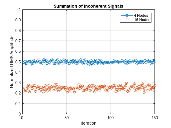
As can be seen, when 4 nodes are considered, the received amplitude at the base station is on average half of the maximum achievable amplitude. In the case of 16 nodes, the RMS amplitude for noncoherent summation is on average 25% of the achievable maximum RMS amplitude if the nodes are fully synchronized. The importance of coherent beamforming is clear once the beamforming nodes are fully synchronized, especially if a high number of nodes is used.
Summary
This example shows how to synchronize distributed nodes to enable beamforming. Frequency and phase synchronization were of interest, while the beamforming nodes were assumed to be time aligned. The example shows how to estimate the center frequency and phase of GMSK signals. In addition, a 1-bit feedback was extracted from the synchronization signals and was used to determine the appropriate adjustment to the phase of the transmitted coherent signals from every node. The beamforming results were compared to the case where the transmitted signals were summed incoherently.
Reference
[1] F. Quitin, M. M. U. Rahman, R. Mudumbai, and U. Madhow, “A scalable architecture for distributed transmit beamforming with commodity radios: Design and proof of concept,” IEEE Trans. Wireless Commun., vol. 12, no. 3, pp. 1418–1428, Mar. 2013.
[2] M. Morelli and U. Mengali, “Feedforward carrier frequency estimation with MSK-type signals,” IEEE Commun. Lett., vol. 2, no. 8, pp. 235– 237, Aug. 1998.
[3] H. Peng, J. Li, and L. Ge, “Non-data-aided carrier frequency offset estimation of GMSK signals in burst mode transmission,” in Proc. 2003 IEEE International Conf. Acoustics, Speech, Signal Process., vol. 4, pp. 576–579.
[4] S. Prager, M. S. Haynes, and M. Moghaddam, "Wireless subnanosecond RF synchronization for distributed ultrawideband software-defined radar networks," IEEE Trans. Microw. Theory Techn., vol. 68, no. 11, pp. 4787–4804, Nov. 2020.
Supporting Functions
helperVarInitialization Function
function [fOffsetEstBnRx,fCorrBnRx,fCorrBnTx,fcBnTxAct,phaseCurrentCorrBnTx,...
    phaseTotalCorrBnTx,phaseBnTxAct,phaseOffsetActBnRx,phaseOffsetActBnTx,...
    phaseOffsetEstBnTx,phaseOffsetEstBnRx] = helperVarInitialization(iterNbr, nodeNbr)

% Helper function that initializes part of the variables.

fOffsetEstBnRx = zeros(1,nodeNbr); % Estimated Frequency offset by each node (Hz)
fCorrBnRx  = zeros(1,nodeNbr); % Frequency added at the beamforming node RX to correct for the offset (Hz)
fCorrBnTx  = zeros(iterNbr,nodeNbr); % Frequency added at beamforming node Tx to correct for the offset (Hz)
fcBnTxAct  = zeros(iterNbr,nodeNbr); % Actual Tx carrier frequency for the beamforming nodes (Hz)
phaseCurrentCorrBnTx = zeros(1,nodeNbr); % Current phase increment added at the beamforming node Tx to correct for the offset (rad)
phaseTotalCorrBnTx = zeros(iterNbr,nodeNbr); % Total phase added at the beamforming node Tx to correct for the offset (rad)
phaseBnTxAct       = zeros(iterNbr,nodeNbr); % phaseOffsetBnTx + phaseTotalCorrBnTx (rad)
phaseOffsetActBnRx = zeros(1,nodeNbr); % Actual phase offset of incoming synchronization signals for each node (rad)
phaseOffsetActBnTx = zeros(iterNbr,nodeNbr); % Actual phase offset of transmitted CW signals from each node (rad)
phaseOffsetEstBnTx = zeros(iterNbr,nodeNbr); % Estimated phase offset of transmitted CW signals from each node (rad)
phaseOffsetEstBnRx = zeros(1,nodeNbr); % Estimated phase offset of incoming synchronization signals for each node (rad)
end
helperFrequencyEstimation Function
function fOffsetEst = helperFrequencyEstimation(wave, fs, samplesPerSymbol)

% Helper function that estimates the frequency of the GMSK signals.

% Waveform transformation to extract the frequency shift
% fs should be high enough to support high samplesPerSymbol values in z
z = (-1).^(0:(length(wave)/samplesPerSymbol) -1).*(wave(1:samplesPerSymbol:end).').^2;

zPadded  = [z(:);zeros(length(z)*7,1)];
freqBbRX = fft(zPadded);
freqShiftedBbRX    = fftshift(freqBbRX);
freqShiftedAbsBbRX = abs(freqShiftedBbRX);
l  = length(zPadded);
dF = fs/l;
f  = (-fs/2:dF:fs/2 - dF);

% Locating the spectrum's peak
[peak,locs] = findpeaks(freqShiftedAbsBbRX);
[~,maxPeakIndex] = max(peak);
maxPeakLoc = locs(maxPeakIndex);
% Frequency estimate refinement
[~,freqEs] = refinepeaks(freqShiftedAbsBbRX, maxPeakLoc, f);

% Frequency of the downconverted GMSK signal
fOffsetEst  = freqEs/(2*samplesPerSymbol);
end
helperPhaseEstimation Function
function refinedTheta = helperPhaseEstimation(fCWave, headerSignal)

% Helper function that estimates the initial phase of the received signals.

% Correlation of frequency-compensated waveform with the header
gamma        = xcorr(fCWave,headerSignal);
% Peak of gamma
gammaAbs     = abs(gamma);
[peak,locs]  = findpeaks(gammaAbs);
[~,maxPeakIndex] = max(peak);
maxPeakLoc  = locs(maxPeakIndex);
% Peak refinement
[~,newPeak] = refinepeaks(gammaAbs, maxPeakLoc);

% Angle estimation from gamma
theta          = angle(gamma);
thetaUnwrapped = unwrap(theta);
% Angle estimate refinement using linear interpolation
[refinedThetaUnwrapped] = interp1(1:length(thetaUnwrapped),thetaUnwrapped,newPeak,'linear');
refinedTheta   = mod(refinedThetaUnwrapped,2*pi);
end
helperPlotResults Function
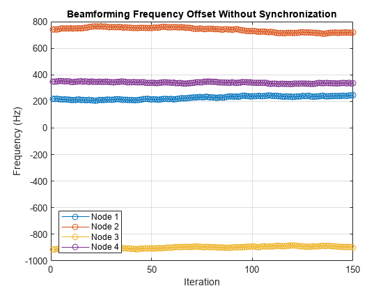
function helperPlotResults(iter, rmsSigBBsRx, phaseTotalCorrBnTx, fcBnTx, fcBnTxAct, fOffsetBnRx)

% Helper function that plots the synchronization and distributed beamforming results.

iterPlt = max(iter,2);

nodeNbr = size(phaseTotalCorrBnTx,2);
legendText = cell(1,nodeNbr);
for i = 1:nodeNbr
legendText{i} = sprintf('Node %s',int2str(i));
end

figure
plot(fOffsetBnRx(1:iterPlt,:),'-o'); grid on
title('Beamforming Frequency Offset Without Synchronization')
xlabel('Iteration');ylabel('Frequency (Hz)')
legend(legendText,'Location','southwest')

figure
plot(fcBnTxAct(1:iterPlt,:) - fcBnTx,'-o'); grid on;
title('Beamforming Frequency Offset With Synchronization')
xlabel('Iteration'); ylabel('Frequency (Hz)')
legend(legendText,'Location','southwest')

figure
plot(rad2deg(phaseTotalCorrBnTx(1:iterPlt,:)),'-o'); grid on
ylim([-180 180])
title('Phase Adjustments for the Beamforming Nodes')
xlabel('Iteration'); ylabel('Phase (\circ)')
legend(legendText,'Location','southwest')

figure
plot(rmsSigBBsRx(1:iterPlt),'-o'); grid on
ylim([0 1])
title('Beamforming Performance')
xlabel('Iteration'); ylabel('Normalized RMS Amplitude')
end