IMU
IMU simulation model
Libraries:
Sensor Fusion and Tracking Toolbox /
Multisensor Positioning /
Sensor Models
Navigation Toolbox /
Multisensor Positioning /
Sensor Models
Description
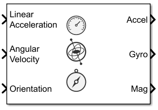
The IMU
Simulink® block models receiving data from an inertial measurement unit (IMU) composed of
accelerometer, gyroscope, and magnetometer sensors. You can specify the reference frame of the
block inputs as the NED (North-East-Down) or ENU
(East-North-Up) frame by using the Reference Frame parameter.
Examples

IMU Sensor Fusion with Simulink
Generate and fuse IMU sensor data using Simulink®. You can accurately model the behavior of an accelerometer, a gyroscope, and a magnetometer and fuse their outputs to compute orientation.
Ports
Input
Output
Parameters
Algorithms
The following algorithm description assumes an NED navigation frame. The accelerometer model
uses the ground-truth orientation and acceleration inputs and the imuSensor
and accelparams properties to
model accelerometer readings.

To obtain the total acceleration (totalAcc), the acceleration is preprocessed by negating and adding the gravity constant vector (g= [0; 0; 9.8] m/s2 assuming an NED frame) as:
The acceleration term is negated to obtain zero
total acceleration readings when the accelerometer is in a free fall. The
acceleration term is also known as the specific force.
Then the total acceleration is converted from the local navigation frame to the sensor frame using:
If the orientation is input in quaternion form, it is converted to a rotation matrix before processing.
The ground-truth acceleration in the sensor frame, a, passes through the bulk model, which adds axes misalignment and bias:
where ConstantBias is a property of accelparams, and α1, α2, and α3 are given by the first, second, and third elements of the AxesMisalignment property of accelparams.
The bias instability drift β1 is modeled as white noise biased and then filtered:
where k is the discrete time step index, BiasInstability is
a property of accelparams,
w is white noise that follows a normal distribution of mean 0 and
variance of 1. The discrete time step size is the reciprocal of the SampleRate
property. [g1,
g2, …,
gn+1] are the
denominator coefficients specified in the
BiasInstabilityCoefficients property of the accelparams object.
[f1,
f2, …,
fm+1] are the
numerator coefficients of the BiasInstabilityCoefficients property.
n and m are the orders of the denominator and
numerator coefficients, respectively.
White noise drift is modeled by multiplying elements of the white noise random stream by the standard deviation:
where w is white noise that follows a normal
distribution of mean 0 and variance of 1, SampleRate is an
imuSensor property, and NoiseDensity is an
accelparams property.
The scale variable s = 2 if the NoiseType
property of the accelparams object is
double-sided and s = 1 if the NoiseType
property is single-sided.
The random walk drift is modeled by biasing elements of the white noise random stream and then filtering:
where k is the discrete time step index, RandomWalk is a
property of accelparams, SampleRate is a
property of imuSensor, w is white noise that follows
a normal distribution of mean 0 and variance of 1. The discrete time step size is the
reciprocal of the SampleRate
property. The scale variable s = 2 if the
NoiseType property of the accelparams object is
double-sided and s = 1 if the NoiseType
property is single-sided.
The environmental drift noise is modeled by multiplying the temperature difference from a standard with the temperature bias:
where Temperature is a property of imuSensor, and TemperatureBias is a property of accelparams. The constant 25 corresponds to a standard temperature.
The temperature scale factor error is modeled as:
where Temperature is a property of imuSensor, and TemperatureScaleFactor is a property of accelparams. The constant 25 corresponds to a standard temperature.
The quantization is modeled by first saturating the continuous signal model:
and then setting the resolution:
where MeasurementRange is a property of accelparams.
The following algorithm description assumes an NED navigation frame. The gyroscope model uses
the ground-truth orientation, acceleration, and angular velocity inputs, and the
imuSensor and gyroparams
properties to model accelerometer readings.

The ground-truth angular velocity is converted from the local frame to the sensor frame using the ground-truth orientation:
If the orientation is input in quaternion form, it is converted to a rotation matrix before processing.
The ground-truth angular velocity in the sensor frame, a, passes through the bulk model, which adds axes misalignment and bias:
where ConstantBias is a property of gyroparams, and α1, α2, and α3 are given by the first, second, and third elements of the AxesMisalignment property of gyroparams.
The bias instability drift β1 is modeled as white noise biased and then filtered:
where k is the discrete time step index, BiasInstability is
a property of gyroparams,
w is white noise that follows a normal distribution of mean 0 and
variance of 1. The discrete time step size is the reciprocal of the SampleRate
property. [g1,
g2, …,
gn+1] are the
denominator coefficients specified in the
BiasInstabilityCoefficients property of the gyroparams object.
[f1,
f2, …,
fm+1] are the
numerator coefficients of the BiasInstabilityCoefficients property.
n and m are the orders of the denominator and
numerator coefficients, respectively.
White noise drift is modeled by multiplying elements of the white noise random stream by the standard deviation:
where w is white noise that follows a normal
distribution of mean 0 and variance of 1, SampleRate is an
imuSensor property, and NoiseDensity is an
gyroparams property.
The scale variable s = 2 if the NoiseType
property of the gyroparams object is
double-sided and s = 1 if the NoiseType
property is single-sided.
The random walk drift is modeled by biasing elements of the white noise random stream and then filtering:
where k is the discrete time step index, RandomWalk is a
property of gyroparams, SampleRate is a
property of imuSensor, and w is white noise that
follows a normal distribution of mean 0 and variance of 1. The discrete time step size
is the reciprocal of the SampleRate
property. The scale variable s = 2 if the
NoiseType property of the gyroparams object is
double-sided and s = 1 if the NoiseType
property is single-sided.
The environmental drift noise is modeled by multiplying the temperature difference from a standard with the temperature bias:
where Temperature is a property of imuSensor, and TemperatureBias is a property of gyroparams. The constant 25 corresponds to a standard temperature.
The acceleration bias drift is modeled by multiplying the acceleration input and acceleration bias:
where AccelerationBias is
a property of gyroparams.
The temperature scale factor error is modeled as:
where Temperature is a property of imuSensor, and TemperatureScaleFactor is a property of gyroparams. The constant 25 corresponds to a standard temperature.
The quantization is modeled by first saturating the continuous signal model:
and then setting the resolution:
where MeasurementRange is a property of gyroparams.
The following algorithm description assumes an NED navigation frame. The magnetometer model
uses the ground-truth orientation and acceleration inputs, and the
imuSensor and magparamsmagparams (Sensor Fusion and Tracking Toolbox)
properties to model magnetometer readings.

The ground-truth acceleration is converted from the local frame to the sensor frame using the ground-truth orientation:
If the orientation is input in quaternion form, it is converted to a rotation matrix before processing.
The ground-truth acceleration in the sensor frame, a, passes through the bulk model, which adds axes misalignment and bias:
where ConstantBias is a property of magparams, and α1, α2, and α3 are given by the first, second, and third elements of the AxesMisalignment property of magparams.
The bias instability drift β1 modeled as white noise biased and then filtered:
where k is the discrete time step index, BiasInstability is
a property of magparams,
w is white noise that follows a normal distribution of mean 0 and
variance of 1. The discrete time step size is the reciprocal of the SampleRate
property. [g1,
g2, …,
gn+1] are the
denominator coefficients specified in the
BiasInstabilityCoefficients property of the magparams object.
[f1,
f2, …,
fm+1] are the
numerator coefficients of the BiasInstabilityCoefficients property.
n and m are the orders of the denominator and
numerator coefficients, respectively.
White noise drift is modeled by multiplying elements of the white noise random stream by the standard deviation:
where w is white noise that follows a normal
distribution of mean 0 and variance of 1, SampleRate is an
imuSensor property, and NoiseDensity is an
magparams property.
The scale variable s = 2 if the NoiseType
property of the magparams object is
double-sided and s = 1 if the NoiseType
property is single-sided.
The random walk drift is modeled by biasing elements of the white noise random stream and then filtering:
where k is the discrete time step index, RandomWalk is a
property of magparams, SampleRate is a
property of imuSensor, w is white noise that follows
a normal distribution of mean 0 and variance of 1. The discrete time step size is the
reciprocal of the SampleRate
property. The scale variable s = 2 if the
NoiseType property of the magparams object is
double-sided and s = 1 if the NoiseType
property is single-sided.
The environmental drift noise is modeled by multiplying the temperature difference from a standard with the temperature bias:
where Temperature is a property of imuSensor, and TemperatureBias is a property of magparams. The constant 25 corresponds to a standard temperature.
The temperature scale factor error is modeled as:
where Temperature is a property of imuSensor, and TemperatureScaleFactor is a property of magparams. The constant 25 corresponds to a standard temperature.
The quantization is modeled by first saturating the continuous signal model:
and then setting the resolution:
where MeasurementRange is a property of magparams.