Register 3-D Multimodal Medical Image Volumes Using Anatomical Landmarks
This example shows how to use control point registration to align CT and MRI scans of the head. Control point registration involves selecting the same landmarks, or control points, in two images and calculating the transformation that aligns the control points. The control points can be identifiable anatomical structures or artificial markers that are visible in both images. You can perform control point registration by using the fitgeotform3d function.
Control point registration algorithms operate on only the control point coordinates and not the image intensities, which generally makes control point registration simpler, faster, and more robust to variations in image intensity than intensity-based registration techniques. However, control point registration is highly sensitive to the accuracy of the control point selection, and is not suitable for image pairs that do not contain the same clearly visible landmarks.
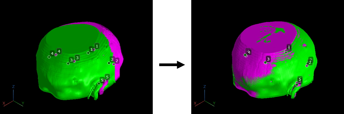
This image shows a pair of CT and MRI volumes before and after control point registration.
Load Images
The data used in this example is a modified version of the 3-D CT and MRI data sets from The Retrospective Image Registration Evaluation (RIRE) Dataset, provided by Dr. Michael Fitzpatrick. For more information, see the RIRE Project homepage. The modified data set contains one CT scan and one MRI scan from the same patient stored in the NRRD file format. The size of the entire data set is approximately 35 MB. Download the data set from the MathWorks® website, then unzip the folder.
zipFile = matlab.internal.examples.downloadSupportFile("medical", ...
    "MedicalRegistrationNRRDdataLPS.zip");
filepath = fileparts(zipFile);
unzip(zipFile,filepath)
Read the CT image into a medicalVolume object.
filenameCT = fullfile(filepath,"supportfilesNRRD","Patient007CT.nrrd");
movingCTVolume = medicalVolume(filenameCT);
Read the MRI image into a medicalVolume object.
filenameMRI = fullfile(filepath,"supportfilesNRRD","Patient007MRT1.nrrd");
fixedMRIVolume = medicalVolume(filenameMRI);
Define Control Point Pairs
Specify the control point coordinates. In this example, you use control points corresponding to anatomical landmarks. The coordinates represent slice numbers, in voxels, and have been picked by using orthosliceViewer.
leftEyeCT = [153 303 6];
leftEyeMRI = [64 154 2];

rightEyeCT = [154 209 5];
rightEyeMRI = [64 106 4];

straightSinusCT = [291 254 13];
straightSinusMRI = [134 129 11];

leftEarAttachCT = [264 368 7];
leftEarAttachMRI = [119 186 5];

rightEarAttachCT = [266 142 6];
rightEarAttachMRI = [120 71 4];

movingCTPoints = [leftEyeCT; rightEyeCT; straightSinusCT;
    leftEarAttachCT; rightEarAttachCT];
fixedMRIPoints = [leftEyeMRI; rightEyeMRI; straightSinusMRI;
    leftEarAttachMRI; rightEarAttachMRI];
This representative image shows how coordinates have been picked for the right-eye control point.
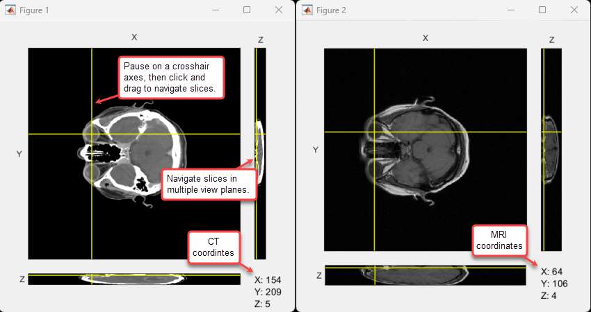
Optionally, if you want to select different control points, use this code to open orthosliceViewer figures for the moving and fixed volumes, enabling you to compare the volumes side by side.
orthosliceViewer(movingCTVolume.Voxels,DisplayRange=[-130 275]);
figure
orthosliceViewer(fixedMRIVolume.Voxels);
Convert Control Points to Patient Coordinate System
The orthosliceViewer uses a coordinate system that labels row indices as Y and column indices as X. To specify coordinates in the format [row, column, slice], which is required for the intrinsicToWorld object function, reorder the first two dimensions of the control point coordinates.
movingCTPoints = movingCTPoints(:,[2 1 3]);
fixedMRIPoints = fixedMRIPoints(:,[2 1 3]);
For each volume, convert the control point locations from intrinsic coordinates to patient coordinates by using the intrinsicToWorld function.
[movX,movY,movZ] = intrinsicToWorld(movingCTVolume.VolumeGeometry, ...
    movingCTPoints(:,1),movingCTPoints(:,2),movingCTPoints(:,3));
movingCTPointsPatient = [movX movY movZ];

[fixedX,fixedY,fixedZ] = intrinsicToWorld(fixedMRIVolume.VolumeGeometry, ...
    fixedMRIPoints(:,1),fixedMRIPoints(:,2),fixedMRIPoints(:,3));
fixedMRIPointsPatient = [fixedX fixedY fixedZ];
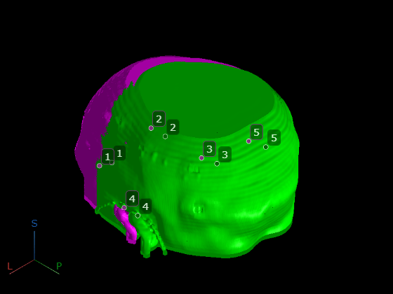
Display Unregistered Volumes
Create a 3-D viewer display of both volumes.
viewerUnregistered = viewer3d(BackgroundColor="black",BackgroundGradient="off");
Display the medicalVolume objects as 3-D isosurfaces using volshow. Display the CT volume in green and the MRI volume in magenta. The volshow function uses the spatial metadata of the medicalVolume objects to display the volumes in patient coordinates.
volshow(movingCTVolume, ...
    Parent=viewerUnregistered, ...
    RenderingStyle="Isosurface", ...
    Colormap="green");

volshow(fixedMRIVolume, ...
    Parent=viewerUnregistered, ...
    RenderingStyle="Isosurface", ...
    Colormap="magenta");
Display the control points as Point annotation objects.
for i = 1:size(fixedMRIPointsPatient,1)
    pmoving(i) = images.ui.graphics3d.roi.Point(Position=movingCTPointsPatient(i,:), ...
        Label=num2str(i), ...
        Color=[0.0 0.4 0.0]);
    pfixed(i) = images.ui.graphics3d.roi.Point(Position=fixedMRIPointsPatient(i,:), ...
        Label=num2str(i), ...
        Color=[0.5 0.2 0.5]);
end

viewerUnregistered.Annotations = [pmoving pfixed];
pause(0.5)
viewerUnregistered.CameraZoom = 2;
pause(0.5)
Calculate Patient-to-Patient Transformation
Fit the transformation that maps movingCTPointsPatient to fixedMRIPointsPatient. Because the control points are in patient coordinates, tform maps from the patient coordinates of the CT volume to the patient coordinates of the MRI volume.
You can specify the type of transform to fit as translation, rigid, or affine. The transform type affects the minimum number of control points required, as well as the type of misalignment the registration can correct for. For example, a rigid transform requires at least three control point pairs and can correct for translation and rotation errors, while an affine transform requires at least four control point pairs and can additionally correct for scaling, reflection, and shear. Given that the CT and MRI volumes in this example originate from the same patient at the same time, we do not expect scaling or shear errors. Therefore, a rigid transformation is sufficient to correct for translations and rotations caused by patient positioning within the different scanners.
tform = fitgeotform3d(movingCTPointsPatient,fixedMRIPointsPatient,"rigid");Calculate Composite Transformation
To align the CT volume with the MRI volume, calculate the composite transformation that
Defines the initial position of the CT volume in patient coordinates.
Applies the registration transformation,
tform.
Obtain the initial position of the CT volume in patient coordinates by using the intrinsicToWorldMapping object function.
movingIntr2World = intrinsicToWorldMapping(movingCTVolume.VolumeGeometry);
Create the composite transformation by multiplying the transformation matrices. To apply movingIntr2World and then tform, list tform first and movingIntr2World second in the multiply operation.
A = tform.A*movingIntr2World.A;
Create an affine transformation object for the transformation matrix.
tformComposite = affinetform3d(A);
Update Spatial Referencing of Moving Volume
In this section, you create a medicalVolume that contains the CT volume image with updated spatial referencing. First, create a new medicalref3d object that defines a volume the same size as the CT data, in voxels, with spatial referencing defined by the composite transformation tformComposite.
volSizeCT = size(movingCTVolume.Voxels);
newref3d = medicalref3d(volSizeCT,tformComposite);
Next, match the PatientCoordinateSystem property of newref3d to that of the CT and MRI volumes.
newref3d.PatientCoordinateSystem = movingCTVolume.VolumeGeometry.PatientCoordinateSystem;
Finally, create a new medicalVolume object that contains the CT volume voxels and the new medicalref3d object. Note that the fixed and transformed moving volumes are aligned when you display them in patient coordinates, but their underlying voxel data still has different voxel spacing and a different number of voxels in each dimension.
transformedCTVolume = medicalVolume(movingCTVolume.Voxels,newref3d);
Resample Voxels of Moving Volume
To overlay 2-D slices from each volume, or use array indexing to analyze the same region in both volumes, you must resample the voxel data of the transformed CT volume so that it has the same number of rows, columns, and slices as the MRI volume.
Resample the transformed CT volume in the coordinate system of the medicalref3d object from the MRI volume by using the resample object function. To avoid edge artifacts, specify the fill value as the minimum of the CT data.
transformedCTVolumeRes = resample(transformedCTVolume, ...
    fixedMRIVolume.VolumeGeometry, ...
    FillValue=-1024);
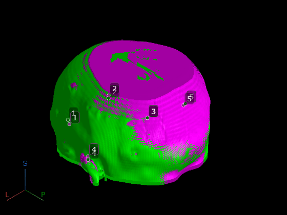
Display Registered Volumes
Display the registered volumes in a new 3-D viewer. Display the CT volume in green and the MRI volume in magenta.
viewerRegistered = viewer3d(BackgroundColor="black",BackgroundGradient="off");

volshow(transformedCTVolumeRes, ...
    RenderingStyle="Isosurface", ...
    Parent=viewerRegistered, ...
    Colormap="green");

volshow(fixedMRIVolume, ...
    RenderingStyle="Isosurface", ...
    Parent=viewerRegistered, ...
    Colormap="magenta");
To visually check that the control points are now aligned, apply the patient-to-patient transform to the CT control points, and display them alongside the MRI control points.
transformedCTPoints = transformPointsForward(tform,movingCTPointsPatient);

for i = 1:size(fixedMRIPointsPatient,1)
    pmoving(i) = images.ui.graphics3d.roi.Point(Position=transformedCTPoints(i,:), ...
        Label=num2str(i), ...
        Color=[0.0 0.4 0.0]);
    pfixed(i) = images.ui.graphics3d.roi.Point(Position=fixedMRIPointsPatient(i,:), ...
        Label=num2str(i), ...
        Color=[0.5 0.2 0.5]);
end

viewerRegistered.Annotations = [pmoving pfixed];
pause(0.5)
viewerRegistered.CameraZoom = 2;
pause(0.5)
Display Registered Volumes as 2-D Slices
To examine the alignment of the volumes in each plane, display the registered volumes as 2-D slices. First, create a fused RGB image volume that overlays the CT volume in green and the MRI volume in magenta. Loop through the transverse slices of the volumes, using the imfuse function to create the fused image for the current slice, and store the fused slices to a new variable, fusedIm.
for i = 1:size(transformedCTVolumeRes.Voxels,3)
    fusedIm(:,:,:,i) = imfuse(transformedCTVolumeRes.Voxels(:,:,i), ...
        fixedMRIVolume.Voxels(:,:,i),method="falsecolor");
end
Permute the dimensions of fusedIm from spatial-spatial-channel-spatial to spatial-spatial-spatial-channel, where channel corresponds to the number of color channels in the fused RGB image.
fusedIm2 = permute(fusedIm,[1 2 4 3]);
Create a medicalVolume object that contains the fused image data and the spatial referencing from the MRI volume.
fusedVol = medicalVolume(fusedIm2,fixedMRIVolume.VolumeGeometry);
Display the fused volume in patient coordinates. To scroll through slices, pause on one of the slices until it highlights, then drag the slice along the axis perpendicular to the plane.
volshow(fusedVol,RenderingStyle="SlicePlanes")
See Also
fitgeotform3d | medicalVolume | medicalref3d | resample
Related Examples
- Register Multimodal Medical Image Volumes with Spatial Referencing
- Align Brain MRI and Dynamic PET Data
More About
Select a Web Site
Choose a web site to get translated content where available and see local events and offers. Based on your location, we recommend that you select: United States.
You can also select a web site from the following list
Americas
- América Latina (Español)
- Canada (English)
- United States (English)
Europe
- Belgium (English)
- Denmark (English)
- Deutschland (Deutsch)
- España (Español)
- Finland (English)
- France (Français)
- Ireland (English)
- Italia (Italiano)
- Luxembourg (English)
- Netherlands (English)
- Norway (English)
- Österreich (Deutsch)
- Portugal (English)
- Sweden (English)
- Switzerland
- United Kingdom (English)
Asia Pacific
- Australia (English)
- India (English)
- New Zealand (English)
- 中国
- 日本Japanese (日本語)
- 한국Korean (한국어)