Calibration Guidelines
These guidelines help you achieve accurate results for lidar camera calibration. For more information on lidar camera calibration, see What Is Lidar-Camera Calibration?
Checkerboard Guidelines
When using the
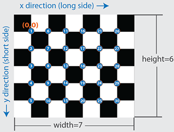
checkerboardfunction to create a checkerboard image:Create a rectangular checkerboard that contains an even number of squares along one edge and an odd number of squares along the adjacent edge. This ensures that the calibration pattern is asymmetric. Symmetric checkerboards can produce inaccurate results and are not recommended.
You can use the length differences of sides and the different corner colors to determine the orientation and the origin of the checkerboard. The Lidar Camera Calibrator app assigns the x-direction to the longer side of the checkerboard. Do not use symmetric checkerboards for calibration workflows since the origin of the board is ambiguous and could be at any of the black corners.
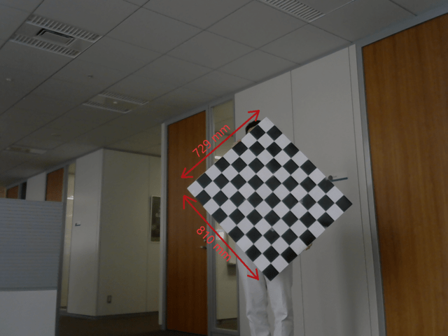
Print the checkerboard pattern from end-to-end and mount it on a foam board, as shown in this figure, to avoid any measurement errors.
Accurately measure any padding you add along each side of the checkerboard. Padding values must be specified as a vector to the Lidar Camera Calibrator app or
estimateBoardCornersCamerafunction when you estimate the checkerboard corners. This figure shows the order of elements of the padding vector, clockwise from the left side of the checkerboard.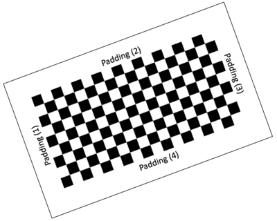
Guidelines for Capturing Data
Capture data from both sensors simultaneously with no motion blur effects. Motion blur can degrade the accuracy of the calibration. If you are working with a video recording, carefully capture the point clouds corresponding to the respective image frames.
The checkerboard should point towards the front axes of the camera (z-axis) and lidar sensor (x-axis).
Hold the checkerboard target with your arms fully extended, rather than close to your body. Otherwise, parts of your body may appear to be planar with the target. This can cause inaccurate checkerboard detection.
For sparse lidar sensors, hold the target from behind, rather than on the edges, because the
estimateBoardCornersLidarfunction searches for the checkerboard plane in each cluster of the input point cloud. To further reduce false detections, specify the approximate checkerboard position using theROIname-value argument.Be aware of the viewing angle or the field of view of the lidar sensor. Do not place the board in the blindspots of the sensor.
Pay close attention to the distance between the sensor and the checkerboard. Low resolution lidar sensors, such as the Velodyne® VLP-16, can have trouble accurately detecting distant checkerboards.
Remove other items from the checkerboard plane to avoid clustering them with the checkerboard data.
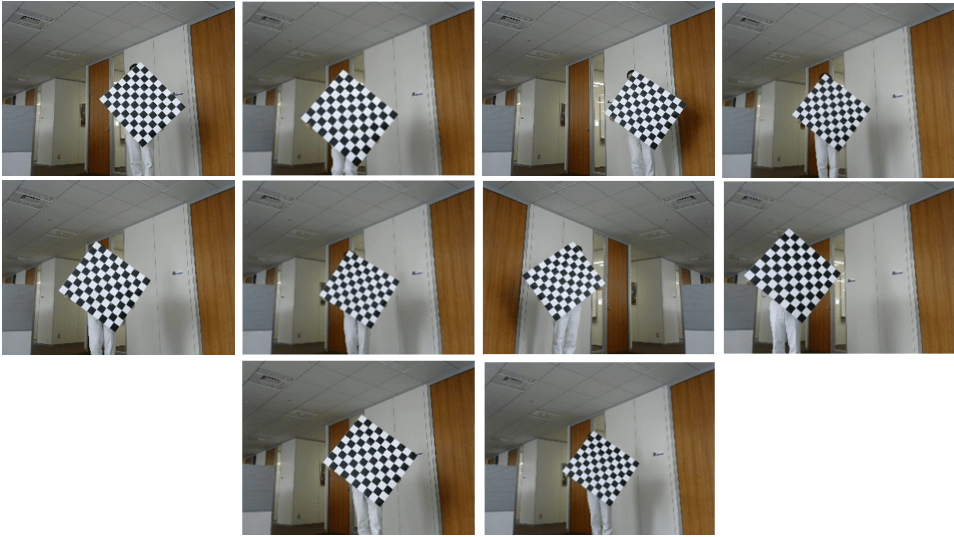
For high-resolution lidar sensors like the HDL-64 and Ouster OS1-64, you can hold the checkerboard horizontally or vertically while capturing data. However, for best results, tilt the checkerboard to a 45-degree angle while capturing data.
This figure shows different ways to hold the checkerboard while capturing data. Capture at least 10 frames for accurate calibration.
You must save point cloud data in the PCD or PLY format.
Image files can be in any standard image format supported by MATLAB®.
For more details on the calibration workflow, see the Lidar Camera Calibration and Fusion example.
See Also
Lidar Camera
Calibrator | estimateBoardCornersLidar | estimateBoardCornersCamera | estimateLidarCameraTransform | projectLidarPointsOnImage | fuseCameraToLidar