Prepare DUT for UVM Framework Generation
What Is UVM Framework?
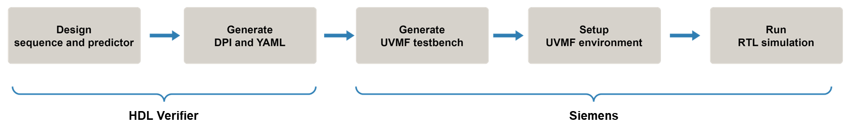
With HDL Verifier™, you can generate DPI components for a UVM sequence and predictor, and then integrate them into a UVM framework (UVMF) testbench for block-level verification.
Use the uvmfbuild
function or the uvmfTestBenchConfiguration object to generate sequence and predictor components
from MATLAB® or Simulink®, respectively. This step also generates a YAML file for UVMF. Once you have
these artifacts, you can use them with Siemens® UVMF tools to generate a UFMV testbench. For an example, see Generate UVM Framework Testbench for Block-Level Verification.
HDL DUT Requirements
Due to the limitations of UVMF tools, your HDL DUT must meet the following requirements:
The DUT must be written in Verilog® or SystemVerilog.
The name of the reset signal must be
rst.The polarity of the reset signal must be active-low.
Multi-dimensional arrays on the interface are not supported.
Using data types (such as
logicorbit) is not supported in the interface declaration. You can specify data types in the module. For example:module adder (clk, rst, addend1, addend2, sum); input logic clk; input logic rst; input logic [15:0] addend1; // uint16 input logic [15:0] addend2; // uint16 output logic [15:0] sum; // uint16The DUT cannot have a clock enable signal.
HDL Coder DUT Requirements
If you are using HDL Coder™ to generate the DUT, you must configure the following model settings so that the generated HDL meets the requirements for UVMF generation:
Language (HDL Coder) — Select
VerilogorSystemVerilog. For SystemVerilog code, manually remove any instances of data types in the module declaration.Reset asserted level (HDL Coder) — Select
active-low.Reset input port (HDL Coder) — Specify
rst.Minimize clock enables (HDL Coder) — Make sure the check box is selected (under Additional settings > Ports).
See Also
uvmfbuild | uvmfTestBenchConfiguration