Guided Hardware Setup
Before you can use the features in the HDL Verifier™ Support Package for AMD FPGA and SoC Devices, HDL Verifier Support Package for Intel® FPGA Boards, or HDL Verifier Support Package for Microchip FPGA Boards, you must establish communication between the host computer and the hardware board. After the installer completes the support package installation, it guides you through the process of establishing communication with the hardware board.
If the support package is already installed, you can start the hardware setup by opening
the Add-Ons panel. To open the Add-Ons panel, click the Add-Ons icon
![]() on the left sidebar.
on the left sidebar.
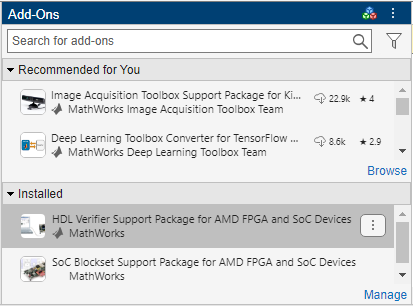
In the Installed section of the Add-Ons panel, start the hardware
setup process by clicking the Options button ![]() next to the installed support package. Then, select
Setup.
next to the installed support package. Then, select
Setup.
Select Board and Interface for Use with FPGA Verification
Choose a hardware board and an interface to use with this board from the list. For the full list of supported boards and interfaces, see Supported FPGA Devices for FPGA Verification. HDL Verifier supports a PCI Express® connection for FPGA-in-the-loop (FIL) with Windows® operating systems only.
The setup process includes the following steps depending on the interface that you select in this step.
Ethernet
Confirm that you have the hardware required to complete the setup process. See Connection Requirements.
Follow the setup steps to set up your hardware board with the Ethernet interface. See Connection Setup.
Configure the network interface card in the host computer. See Configure NIC on Host Computer.
Verify the connection between the host computer and the hardware board. See Verify Setup.
Ethernet on Versal, Zynq, or Intel Agilex 7 SoC Board
Confirm that you have the hardware required to complete the setup process. See Connection Requirements.
Configure the network interface card in the host computer. See Configure NIC on Host Computer.
Copy the compatible secure digital (SD) card image files for the hardware board to an SD card drive path. See Select a Drive and Load Firmware.
Configure your hardware board to start up from the SD card. See Set Jumpers.
Connect your hardware board to the host computer. For a Versal® or Zynq® SoC board, see Connect Hardware. For an Intel Agilex® 7 SoC board, see Connect Intel Agilex 7.
Verify the connection between the host computer and the hardware board. See Verify Setup.
JTAG
Confirm that you have the hardware required to complete the setup process. See Connection Requirements.
Follow the setup steps to set up your hardware board with the JTAG interface. See Connection Setup.
Verify the connection between the host computer and the hardware board. See Verify Setup.
PCI Express
Confirm that you have the hardware required to complete the setup process. See Connection Requirements.
Install the PCIe driver on the host computer. See Install PCI Express Driver.
Configure the jumpers on the hardware board. See Set Jumpers.
Follow the setup steps to set up your hardware board with the PCI Express interface. See Connection Setup.
USB Ethernet
Confirm that you have the hardware required to complete the setup process. See Connection Requirements.
Windows only — Install the USB Ethernet drivers on the host computer. See Install USB Ethernet Drivers.
Copy the compatible SD card image files for the hardware board to an SD card drive path. See Select a Drive and Load Firmware.
Configure the jumpers on the hardware board. See Set Jumpers.
Connect your hardware board to the host computer. See Connect Hardware.
Configure the USB Ethernet or RNDIS gadget on the host computer. See Configure USB on Host Computer.
Verify the connection between the host computer and the hardware board. See Verify Setup.
Connection Requirements
The guided setup wizard displays a checklist of the hardware requirements. Confirm that you have the hardware required to complete the setup process.
Note
Do not connect to the board or turn it on until you are prompted at a later step.
Ethernet Requirements
FPGA or SoC development board
USB-JTAG cable (for FPGA boards only)
Installed Vivado®, Quartus®, or Microchip Libero® SoC software, with a supported version listed in FPGA Verification Requirements (for FPGA boards only)
Dedicated Gigabit network interface card (NIC) or USB 3.0 Gigabit Ethernet adapter dongle
Ethernet cable
Power supply adapter, if the board requires one
Ethernet on Intel Agilex 7 SoC Board Requirements
Intel Agilex 7 SoC Board
Installed Quartus Prime Pro software, with a supported version listed in FPGA Verification Requirements
Dedicated Gigabit NIC or USB 3.0 Gigabit Ethernet adapter dongle
Ethernet cable
Power supply adapter, if the board requires one
SD card reader and writable SD card with a capacity of 4 GB or larger
Ethernet on Versal or Zynq SoC Board Requirements
Versal or Zynq SoC board
Dedicated Gigabit NIC or a USB 3.0 Gigabit Ethernet adapter dongle
Ethernet cable
Power supply adapter, if the board requires one
SD card reader and writable SD card with a capacity of 4 GB or larger
JTAG Requirements
FPGA or SoC development board
USB-JTAG cable
Installed Vivado or Quartus software, with a supported version listed in FPGA Verification Requirements
Installed Digilent® Adept 2 Runtime (for Linux® operating systems on AMD® boards only)
Power supply adapter, if the board requires one
PCI Express Requirements
HDL Verifier supports a PCI Express connection for Windows operating systems only.
FPGA development board
USB-JTAG cable
Installed Vivado or Quartus software, with a supported version listed in FPGA Verification Requirements
PCI Express slot and available space on the motherboard
Power supply adapter, if the board requires one
USB Ethernet Requirements
SoC development board
USB 3.0 or USB 2.0 cable based on the type of USB cable the selected hardware board supports
Note
If you use a USB 2.0 cable for a board that supports USB 3.0, the cable provides lesser data throughput.
Power supply adapter (if the board requires one)
SD card reader and writable SD card with a capacity of 4 GB or larger
Connection Setup
This step is required only when you select the JTAG or PCI Express interface or the Ethernet interface on an FPGA or SoC board other than the Versal, Zynq, and Intel Agilex 7 SoC boards.
The guided setup wizard displays the setup steps for the selected interface. Follow these steps to set up your hardware board with the selected interface.
Ethernet
Ensure that the board power switch is off.
Connect the AC power cord to the power plug, and plug the power supply adapter cable into the hardware board.
Use the crossover Ethernet cable to connect the Ethernet connector on the hardware board directly to the Ethernet adapter on your host computer.
Use the JTAG download cable to connect the hardware board to the host computer.
Make sure that all the jumpers on the hardware board are in the factory default position.
Turn the power switch of the hardware board on.
JTAG
Ensure that the board power switch is off.
Connect the AC power cord to the power plug, and plug the power supply adapter cable into the hardware board.
Use the JTAG download cable to connect the hardware board to the host computer.
Make sure that all the jumpers on the hardware board are in the factory default position.
Turn the power switch of the hardware board on.
PCI Express
Ensure that the board power switch is off.
Select the maximum number of PCI Express lanes that the board supports. For details, refer to the user manual for the board.
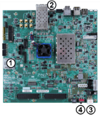
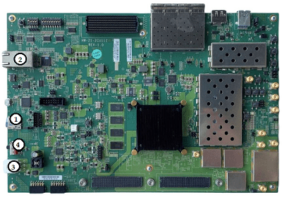
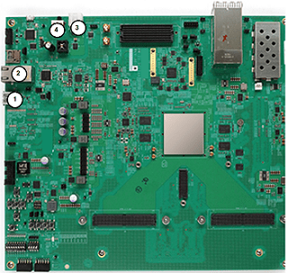
Supported Board PCI Express Setup Documentation DSP Development Kit, Stratix® V Edition Set the three switches (PCIE_PRSNT2nx1, x4, x8) in dip switch SW6 to ON. This setting selects 8-lane PCIe (default board setting). https://www.altera.com/products/development-kits Cyclone® V GT FPGA Development Kit Set the two switches(PCIe_x1, x4) in dip switch SW3 to ON. This setting selects 4-lane PCIe (default board setting). https://www.altera.com/products/devkit/po-3009/cyclone-v-gt-fpga-development-kit Kintex®-7 KC705 Set jumper J32 so that it connects pins 5 and 6. This setting selects 8-lane PCIe (default board setting). https://www.xilinx.com/products/boards-and-kits/ek-k7-kc705-g.html Virtex®-7 VC707 Set jumper J49 so that it connects pins 5 and 6. This setting selects 8-lane PCIe (not the default board setting). https://www.xilinx.com/products/boards-and-kits/ek-v7-vc707-g.html Turn the host computer off.
Install the hardware board in a PCI Express slot inside the host computer.
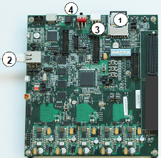
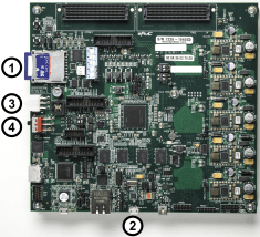
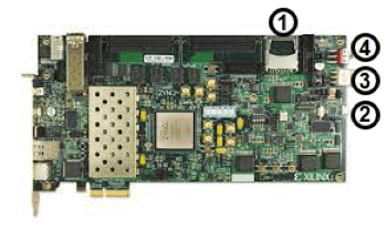
This figure shows the Stratix V board installed in a host computer. This installation applies to all supported Intel VC boards.

This figure shows the VC707 board installed in a host computer. The power cable is on the right. This installation applies to all supported AMD boards.

For AMD boards, plug the external power supply into the wall outlet. Then, plug the power supply adapter cable into the hardware board.
Intel boards do not use an external power supply.
Connect the JTAG cable to the hardware board and the host computer. When you use a PCI Express connection, the JTAG cable is still required to program the FPGA.

Turn the power switch of the hardware board on.
Start up the host computer.
Install USB Ethernet Drivers
This step is required only when you select the USB Ethernet interface on a Windows operating system.
If you have already installed the USB Ethernet drivers, skip this step.
You must install the USB Ethernet drivers before you use AXI manager or FIL with a USB Ethernet connection. To install the drivers, click Install Driver. The installation process might require system administrator privileges.
Configure NIC on Host Computer
This step is required only when you select the Ethernet interface.
In this step, you configure the host computer so that it can communicate with the hardware board. You must have a dedicated Gigabit Ethernet NIC for the hardware board, with an Ethernet cable connecting the card to your hardware board. If you also want simultaneous internet access and you do not have a wireless connection, your host computer requires a second Ethernet NIC. In this case, consider using a USB 3.0 Gigabit Ethernet adapter dongle.
The guided setup supports the NIC configuration on the Windows operating system only. For the Linux operating system, manually configure the NIC by following the steps in Configure Linux.
In the guided setup, select the NIC that you want to connect with the hardware board. If you have already configured the NIC, select Skip this step if your network card is already configured for communicating with the FPGA or SoC board.
The list displays the connected NICs detected on your host computer. The menu options
show each NIC as (In Use) or (Available). The
installer marks an NIC as (In Use) when the NIC is connected to a
device and has an assigned IP address.
If you do not see your NIC listed, click Refresh to trigger the NIC detection and refresh the list. Refreshing the list is useful when, for example, you plug in a USB Ethernet adapter dongle while viewing this pane.
If all the NICs listed are in use, free up a NIC for use with the hardware and then click Refresh.
If the NIC list is empty, VMWare software, if present, can interfere with NIC detection. To get an accurate list of NICs on your host computer, remove the VMWare software.
Check whether the missing NIC is disabled in the control panel. If the NIC is disabled, enable it.
Leave the IP address of the NIC as the default. Alternatively, specify the IP address
in dotted quad format, for example, 192.168.0.1.
When you click Next, the software configures the NIC.
Select a Drive and Load Firmware
This step is required only when you select the USB Ethernet interface or the Ethernet interface on a Versal, Zynq, or Intel Agilex 7 SoC board.
USB Ethernet only — Configure the USB Ethernet interface so that the host computer can communicate with the hardware board. You must have a USB cable connecting the host computer to your hardware board.
In the guided setup, specify the IP address of the USB device in dotted quad format, for example,
192.168.1.2. Leave the IP address of the USB host as the default. When you click Next, the subsequent steps use the USB host IP address to configure the USB Ethernet interface detected on the host computer.Next, the installer must write an FPGA image to an SD card. This FPGA image is included with the support package. The image includes the embedded software and the FPGA programming file necessary for using the hardware board as an I/O peripheral.
Insert a 4 GB or larger SD card into the card reader on the host computer. The card must be in FAT32 format. Select the appropriate drive from the list. If you have already downloaded the FPGA image, skip this step.

Note
Unlock the SD card before downloading the firmware image to the card. Keep the card unlocked while the card is in the board card reader.
Write the FPGA image to the SD card. In the guided setup, select the location of the SD drive containing the card, then click Next. On the next screen, to copy the programming file from the host computer to the SD card, click Write. This process erases any existing data on the card.
Install PCI Express Driver
This step is required only when you select the PCI Express interface.
If you have already installed the PCI Express drivers, you can skip this step.
Install the PCI Express drivers before you use FIL, FPGA data capture, or AXI manager with a PCI Express connection. This step performs the driver installation for you. The process can take 10 or more minutes to install, and might require system administrator privileges.
You can let the support package setup install the drivers now, or you can choose to perform the setup again later. To run the support package setup, on the MATLAB® Home tab, in the Environment section, select Help > Check for Updates.
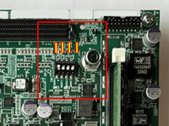
Set Jumpers
This step is required only when you select the PCI Express interface, the USB Ethernet interface, or the Ethernet interface on a Versal, Zynq, or Intel Agilex 7 SoC board.
Configure the jumpers on the hardware board so that you can use it as a peripheral device. These jumper settings make it so that the board starts up from the SD card. Make sure that the board is turned off.
The jumper settings are different for each board. To learn more about the settings, see the board documentation.
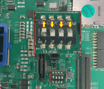
Set Jumpers on Intel Agilex 7
You must configure the Secure Device Manager (SDM) on the Intel Agilex 7 SoC board to manage the security functions. If you have already configured the SDM, skip this step and set the S9 switch positions to on-on-off-off before connecting the hardware.
S9 and Other Switch Positions
| Jumpers | Switch Positions | |||
|---|---|---|---|---|
| Switch 1 | Switch 2 | Switch 3 | Switch 4 | |
| S9 before configuring SDM | On | On | On | Off |
| S9 after configuring SDM | On | On | Off | Off |
| S4 | On | On | On | On |
| S15 | On | On | On | Off |
| S10 | On | On | On | On |
| S23 | On | On | On | On |
| S6 | Off | Off | Off | Off |
| S1 | Off | Off | Off | Off |
| S22 | On | On | On | On |
| S19 | Off | Off | On | On |
| S20 | On | On | On | On |

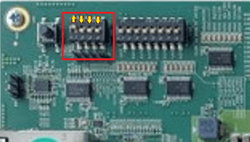
Set Jumpers on Versal VCK190
SW1 Switch Positions
| Switch | Switch Position |
|---|---|
| 1 | Up |
| 2 | Down |
| 3 | Down |
| 4 | Down |
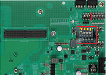
Set Jumpers on ZCU102
SW6 Switch Positions
| Switch | Switch Position |
|---|---|
| 1 | Up |
| 2 | Down |
| 3 | Down |
| 4 | Down |
Set Jumpers for USB Ethernet Configuration
| Jumper | Jumper Position |
|---|---|
| J7 | Off |
| J113 | 1-2 |
| J110 | 1-2 |
| J109 | No jumper |
Set Jumpers on ZCU111
SW6 Switch Positions
| Switch | Switch Position |
|---|---|
| 1 | Up |
| 2 | Down |
| 3 | Down |
| 4 | Down |
Set Jumpers on ZCU208
SW2 Switch Positions
| Switch | Switch Position |
|---|---|
| 1 | Up |
| 2 | Down |
| 3 | Down |
| 4 | Down |

Set Jumpers on ZCU216
SW2 Switch Positions
| Switch | Switch Position |
|---|---|
| 1 | Up |
| 2 | Down |
| 3 | Down |
| 4 | Down |
Set Jumpers on ZC702
JTAG Select Jumper Positions
| Switch | Switch Position |
|---|---|
| Top | Left |
| Bottom | Right |
SW10 Jumper Positions
| Switch | Switch Position |
|---|---|
| 1 | Down |
| 2 | Down |
| 3 | Up |
| 4 | Up |
| 5 | Down |
Set Jumpers for USB Ethernet Configuration
| Jumper | Jumper Position |
|---|---|
| J7 | Off |
| J33 | 1-2 |
| J35 | 1-2 |

Set Jumpers on ZC706
SW11 Jumper Positions
| Switch | Switch Position |
|---|---|
| 1 | Down |
| 2 | Down |
| 3 | Up |
| 4 | Up |
| 5 | Down |
Set Jumpers for USB Ethernet Configuration
| Jumper | Jumper Position |
|---|---|
| J10 | Off |
| J48 | 1-2 |
| J50 | 1-2 |

Set Jumpers on ZedBoard
Jumper Positions
| Switch | Switch Position |
|---|---|
| 1 | Down |
| 2 | Up |
| 3 | Up |
| 4 | Down |
| 5 | Down |
Set Jumpers for USB Ethernet Configuration
| Jumper | Jumper Position |
|---|---|
| JP3 | Open |

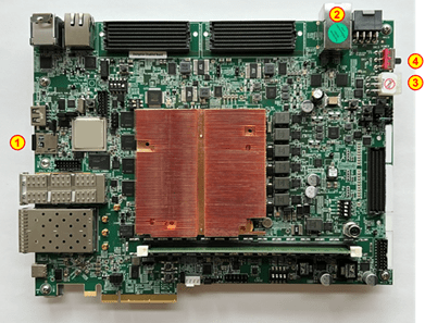
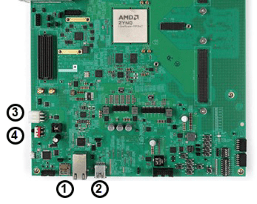
Connect Hardware
This step is required only when you select the USB Ethernet interface or the Ethernet interface on a Versal or Zynq SoC board.
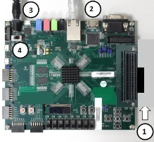
Follow these instructions for connecting the hardware. The guided setup wizard provides labeled pictures of the steps for each board.
Remove the SD card from the host computer and insert it into the hardware board.
Ethernet interface — Connect an Ethernet cable to the board. Connect the other end of the Ethernet cable to the selected NIC.
USB Ethernet interface — Connect a USB cable to the board. Connect the other end of the USB cable to the host computer.
Connect the power cable.
Turn the power on.
Connect VCK190 Board
Connect ZCU102 Board for Ethernet
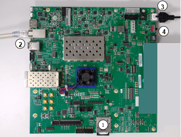
Connect ZCU102 Board for USB Ethernet
Connect ZCU111 Board
Connect ZCU208 Board

Connect ZCU216 Board for Ethernet
Connect ZCU216 Board for USB Ethernet
Connect ZC702 Board for Ethernet
Connect ZC702 Board for USB Ethernet
Connect ZC706 Board for Ethernet

Connect ZC706 Board for USB Ethernet
Connect ZedBoard for Ethernet
Connect ZedBoard for USB Ethernet

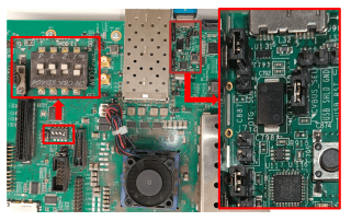
Connect Intel Agilex 7
This step is required only when you select the Ethernet interface on an Intel Agilex 7 SoC board.
To configure the SDM, set the S9 switch positions to on-on-on-off and follow these instructions.
Connect the JTAG cable to the board.
Connect the power cable to the board and turn the power on.
Run this command in the MATLAB Command Window to program the SDM via the JTAG cable.
programSDM
Turn the board power off and set the S9 switch positions to on-on-off-off.
Configure SDM on Intel Agilex 7 SoC Board

After you configure the SDM or when you skip configuring the SDM, set the S9 switch positions to on-on-off-off and follow these instructions for connecting the hardware. The guided setup wizard provides labeled pictures of the steps for the board.
Remove the SD card from the host computer and insert it into the hardware board.
Connect an Ethernet cable to the board. Connect the other end of the Ethernet cable to the selected NIC.
Connect the power cable.
Turn the power on.
Connect Intel Agilex 7 SoC Board

Configure USB on Host Computer
This step is required only when you select the USB Ethernet interface.
Configure the host computer so that it can communicate with the hardware board. You must have a dedicated USB Ethernet or RNDIS gadget for the hardware board, with a USB cable connecting the card to your hardware board.
The guided setup supports the USB configuration on the Windows operating system only. For the Linux operating system, manually configure the USB Ethernet gadget by following the steps in Configure Linux.
For the Windows operating systems, in the guided setup, select the USB Ethernet or RNDIS gadget that you want to connect with the hardware board. If you have already configured the USB Ethernet gadget, select Skip this step if your USB Ethernet gadget is already configured for communicating with the SoC board.
After you boot the SD card on the target hardware board, the board appears on the host computer as the MathWorks® USB Ethernet or RNDIS gadget.
The list displays the connected NICs detected on your host computer. The connected
USB Ethernet gadgets are part of this list. The menu options show each gadget as
(In Use) or (Available). The installer marks a
gadget as (In Use) when the gadget is connected to a device and has
an assigned IP address.
If you do not see your USB Ethernet gadget listed, click Refresh to trigger the gadget detection and refresh the list. Refreshing the list is useful when, for example, you plug in a USB Ethernet cable while viewing this pane.
If all the USB Ethernet gadgets listed are in use, release a gadget and click Refresh.
If the NIC list is empty, VMWare software, if present, can interfere with NIC detection. To get an accurate list of NICs on your host computer, remove the VMWare software.
Check whether the missing USB Ethernet gadget is disabled in the control panel. If the USB Ethernet gadget is disabled, enable it.
Leave the IP address of the USB device and USB host as the default. Alternatively, in
the Select a Drive and Load Firmware step, you can specify the IP address of the USB
device in dotted quad format, for example, 10.10.10.2. When you click
Next, the software configures the USB Ethernet interface on
the host computer based on these network configurations.
Verify Setup
You can verify the hardware setup for Ethernet, JTAG, and USB Ethernet interfaces. This step runs the tests to verify the connection between the host computer and the hardware board based on the selected interface. Before you run the test, make sure that:
You have installed the appropriate vendor tool and that the tool is on the MATLAB path. See Set Up FPGA Design Software Tools.
The board is turned on.
This step runs these tests to verify the connection for the selected interface.
Ethernet
Generate an FPGA programming file for your hardware board.
Program the FPGA.
Detect an Ethernet connection.
Ethernet on Versal or Intel Agilex 7 SoC Board
Verify the IP address configuration on the host computer.
Verify the Ethernet connection between the host computer and the hardware board.
Read and write the memory locations on the hardware board with the default SD card image bitstream.
Ethernet on Zynq SoC Board
Verify the IP address configuration on the host computer.
Verify the Ethernet connection between the host computer and the hardware board.
Read and write the memory locations on the hardware board using AXI manager.
JTAG
Generate an FPGA programming file for your board.
Program the FPGA.
Perform the data transaction between the FPGA and the host computer.
USB Ethernet
Verify the IP address configuration on the host computer.
Verify the Ethernet connection between the host computer and the hardware board.
Read and write the memory locations on the hardware board with the default SD card image bitstream.
If the connection is not successful, the most common reasons are that the board is not connected properly or it is not turned on. Check the cable connections and power switch and try again.
Open Examples
When the installer completes your hardware setup, you can exit the installer or open the examples to get started.