Generate HDL Verification Component for UWB Channel
To verify the hardware design of a transceiver, your simulation should include transmitting and receiving data through a realistic model of wireless channel conditions. This example shows a MATLAB-based workflow to generate a SystemVerilog DPI (SVDPI) component of a channel model. You can integrate the generated component into your HDL verification environment. The channel model is generated from the IEEE®-compliant ultra-wideband (UWB) channel model provided by Communications Toolbox™ functions. The component generation includes a self-checking testbench for verification with an HDL simulator. This testbench verifies that the generated component is equivalent to the original UWB channel.
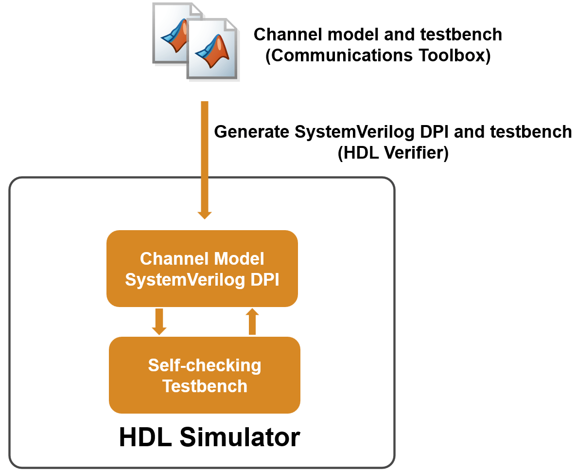
You can then simulate your transceiver's design by integrating the generated SVDPI component into your production HDL verification environment. The workflow is illustrated in the following diagram.
Create UWB Channel and MATLAB Testbench
Create a function that filters an input signal through a UWB IEEE 802.15.4™ a/z/ab channel using the uwbChannel (Communications Toolbox) System object™. To view the example function, enter this command at the MATLAB® prompt:
edit myUWBChannelNext, create a MATLAB testbench function that generates a stimulus and passes it to the myUWBChannel function. In this example, the stimulus is an HPRF IEEE 802.15.4z waveform created by using the lrwpanWaveformGenerator (Communications Toolbox) System object. To view the example MATLAB testbench, enter this command at the MATLAB prompt:
edit myUWBChannel_tbGenerate SystemVerilog DPI Component
Follow these steps to generate the DPI component and a testbench that checks the output of the generated component against the MATLAB function. To allow stimuli of different lengths without regenerating the DPI component each time, configure the DPI component to have variable-length inputs and outputs.
Create a configuration object for a SystemVerilog module, configured to have variable-size inputs and outputs.
Set the toolchain to a supported simulator. Make sure that the specified simulator is on the system path. This example uses the Questa™ simulator. See Supported EDA Tools and Hardware for other supported simulators.
Generate the DPI component and the testbench using the
dpigenfunction. The arguments shown here are:-config cfg: Specify the configuration object ascfgthat you created in step 1 and 2.-testbench myUWBChannel_tb: Generate a SystemVerilog testbench that compares the output of the DPI component with the MATLAB function.-args {coder.typeof(1,[inf 1],[1 0])}: Specify the MATLAB function input to be a double-precision variable-size column vector.
Execute these commands at the MATLAB prompt:
cfg = svdpiConfiguration('sequential-module-varsize');
if ispc
    cfg.CoderConfiguration.Toolchain = "Siemens Questa/Modelsim (64-bit Windows)";
else
    cfg.CoderConfiguration.Toolchain = "Siemens Questa/Modelsim (64-bit Linux)";
end

dpigen -config cfg myUWBChannel -testbench myUWBChannel_tb -args {coder.typeof(1,[inf 1],[1 0])};
### Generating DPI-C Wrapper myUWBChannel_dpi.c
### Generating DPI-C Wrapper header file myUWBChannel_dpi.h
### Generating file myUWBChannel_pkg.sv
### Generating file myUWBChannel.sv
### Generating vsim makefile/script myUWBChannel.do
### Running simulation to capture input and expected outputs for a standalone testbench.
### This may take some time...
Code generation successful.

### ...DONE with test-vector capture.
### Generating file run_tb_mq.do
### Generating file myUWBChannel_tb.sv
Code generation successful.

### Executing simulator script using vsim on system path
### Successful script execution.
This figure shows the generated artifacts.
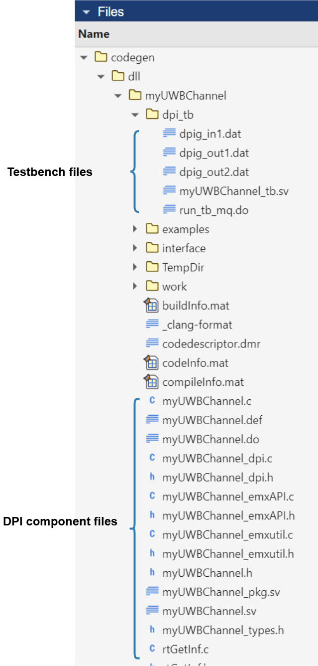
The DPI component files include:
C code generated from the MATLAB function
myUWBChannel.SystemVerilog wrapper code for importing C functions.
The testbench files include:
SystemVerilog testbench that verifies the DPI component output against the data generated from the MATLAB testbench
myUWBChannel_tb.Data files containing the logged inputs and outputs of
myUWBChannel.Script file that automates the simulation process.
Verify SystemVerilog DPI Component
To verify that the behavior of the DPI component matches the MATLAB function, run this command that opens your HDL simulator and simulates the testbench:
cd codegen/dll/myUWBChannel/dpi_tb
[~, result] = system('vsim -c -do run_tb_mq.do')
Reading pref.tcl

# 2024.3_1

# do run_tb_mq.do
# run -all
# ..
# QuestaSim-64 vlog 2024.3_1 Compiler 2024.10 Oct 16 2024
# Start time: 10:01:15 on Oct 15,2025
# vlog "+define+MG_SIM" ../myUWBChannel_pkg.sv ../myUWBChannel.sv ./myUWBChannel_tb.sv
# -- Compiling package myUWBChannel_pkg
# -- Compiling package myUWBChannel_sv_unit
# -- Importing package myUWBChannel_pkg
# -- Compiling interface myUWBChannel_interface
# -- Compiling module myUWBChannel
# -- Compiling package myUWBChannel_tb_sv_unit
# -- Compiling module myUWBChannel_tb
#
# Top level modules:
# 	myUWBChannel_tb
# End time: 10:01:15 on Oct 15,2025, Elapsed time: 0:00:00
# Errors: 0, Warnings: 0
# vsim -c -voptargs="+acc" -L ../work work.myUWBChannel_tb
# Start time: 10:01:16 on Oct 15,2025
# ** Note: (vsim-3812) Design is being optimized...
# ** Warning: (vopt-10587) Some optimizations are turned off because the +acc switch is in effect. This will cause your simulation to run slowly. Please use -access/-debug to maintain needed visibility. The +acc switch would be deprecated in a future release.
# ** Note: (vsim-12126) Error and warning message counts have been restored: Errors=0, Warnings=1.
# //  Questa Sim-64
# //  Version 2024.3_1 win64 Oct 16 2024
# //
# // Unpublished work. Copyright 2024 Siemens
# //
# // This material contains trade secrets or otherwise confidential information
# // owned by Siemens Industry Software Inc. or its affiliates (collectively,
# // "SISW"), or its licensors. Access to and use of this information is strictly
# // limited as set forth in the Customer's applicable agreements with SISW.
# //
# // This material may not be copied, distributed, or otherwise disclosed outside
# // of the Customer's facilities without the express written permission of SISW,
# // and may not be used in any way not expressly authorized by SISW.
# //
# Loading sv_std.std
# Loading work.myUWBChannel_pkg(fast)
# Loading work.myUWBChannel_tb_sv_unit(fast)
# Loading work.myUWBChannel_tb(fast)
# Loading work.myUWBChannel_sv_unit(fast)
# Loading work.myUWBChannel_interface(fast__1)
# Loading work.myUWBChannel(fast)
# Loading C:/Users/user/AppData/Local/Temp\ypeng@MATHWORKS-2YWIP_dpi_7620\win64_gcc-7.4.0\vsim_auto_compile.dll
# Tolerance parameter for floating point comparisons is set to: 4.440892e-16.
# Override the SystemVerilog parameter using the EXTRA_SVDPI_SIM_ARGS or EXTRA_SVDPI_COMP_ARGS appropriate for your simulator.
# **************TEST COMPLETED (PASSED)**************
# ** Note: $finish    : ./myUWBChannel_tb.sv(108)
#    Time: 42 ns  Iteration: 0  Instance: /myUWBChannel_tb
# Vector compare count = 1
# End time: 10:01:50 on Oct 15,2025, Elapsed time: 0:00:34
# Errors: 0, Warnings: 1
Next Steps
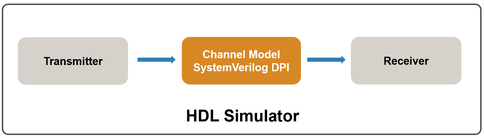
After verifying the DPI component using the auto-generated testbench, you can integrate the DPI component into your HDL production environment to simulate and verify your own designs.
You can apply this approach to generate DPI components for other channel models or wireless waveforms developed with Communications Toolbox functions, and integrate them into the RTL design of your communication system.
You can also generate a Universal Verification Methodology (UVM) component to integrate the behavioral channel model into a UVM environment.
See Also
dpigen | svdpiConfiguration | uwbChannel (Communications Toolbox)