Optimize Clock Speed for MATLAB Code by Using Adaptive Pipelining
R2026bThis example shows how to use the adaptive pipelining optimization in HDL Coder™ to optimize clock speed for a MATLAB® design that implements a symmetric FIR filter.
Certain code patterns with registers can improve achievable clock frequency and reduce area usage on FPGA boards. The adaptive pipelining optimization creates these patterns by inserting pipeline registers in your design. To determine the optimal number of pipeline registers, HDL Coder considers the target device, target frequency, and multiplier word lengths.
Adaptive pipelining also pipelines multiply operations for optimized DSP mapping and supports other optimizations such as resource sharing.
Examine the MATLAB Design and Test Bench
Set up the MATLAB function and test bench for this example. In the MATLAB Command Window, enter:
mlhdlc_demo_setup("mlhdlc_sfir");MATLAB function
Test bench
mlhdlc_sfir1_runme_hdl.mscript, which includes the commands to generate HDL code
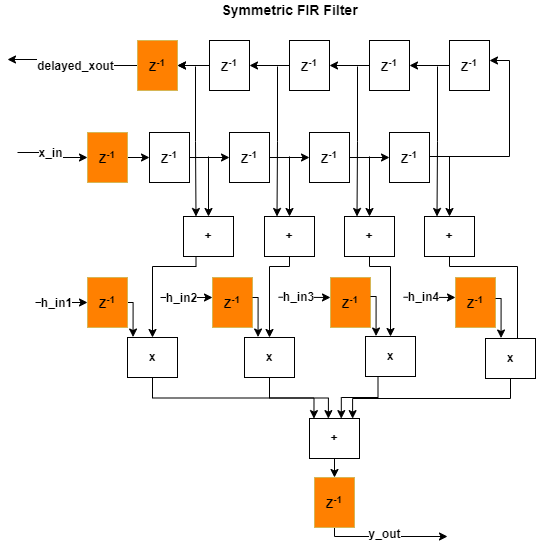
The MATLAB function, mlhdlc_sfir1, implements a symmetric FIR
filter with 8 persistent delay states, 4 symmetric additions, and 4 multiplications.
The function accepts an input sample and four filter coefficients, and returns the
filtered output and a delayed version of the input. To view the function,
enter:
open mlhdlc_sfir1.m;The test bench, mlhdlc_sfir1_tb, generates a noise-modulated
chirp signal and passes 2001 samples through the filter. To view the test bench,
enter:
open mlhdlc_sfir1_tb.m;Simulate the Design
To check for run-time errors, simulate the design by running the test bench. In the MATLAB Command Window, enter:
mlhdlc_sfir1_tb;
Generate HDL Code Without Adaptive Pipelining
Create fixed-point and HDL configuration objects. Specify the design name and test
bench, a synthesis tool and target device, and a target frequency. Set the
InputPipeline and OutputPipeline configuration object
properties to 1 and set LoopOptimization to
"UnrollLoops".
designName = "mlhdlc_sfir1";
designTB = "mlhdlc_sfir1_tb";

fixptCfg = coder.config("fixpt");
fixptCfg.TestBenchName = designTB;

cfg = coder.config("hdl");
cfg.TestBenchName = designTB;
cfg.SynthesisTool = "Xilinx Vivado";
cfg.SynthesisToolChipFamily = "Artix7";
cfg.SynthesisToolDeviceName = "xa7a100t";
cfg.SynthesisToolPackageName = "csg324";
cfg.SynthesisToolSpeedValue = "-1I";
cfg.TargetFrequency = 200;
cfg.InputPipeline = 1;
cfg.OutputPipeline = 1;
cfg.LoopOptimization = "UnrollLoops";
Generate HDL code without adaptive pipelining. To synthesize the generated code and
run place and route, set the SynthesizeGeneratedCode and
PlaceAndRoute configuration object properties to
true.
cfg.AdaptivePipelining = false;
cfg.SynthesizeGeneratedCode = true;
cfg.PlaceAndRoute = true;

codegen("-float2fixed", "fixptCfg", "-config", "cfg", designName, ...
    "-launchreport");
After code generation completes, the report shows two cycles of latency, one cycle each for the input pipeline and output pipeline. The post-implementation results show a negative slack of -3.612 ns, indicating that timing constraints are not met. The clock frequency is 116 MHz, below the 200 MHz target. These results were obtained by using MATLAB R2026b and Xilinx Vivado 2025.1.
This figure shows the hardware implementation of the algorithm without adaptive pipelining. The input and output pipelines are shown in orange.
Generate HDL Code with Adaptive Pipelining
Set the AdaptivePipelining configuration object property to
true and regenerate HDL
code.
cfg.AdaptivePipelining = true;

codegen("-float2fixed", "fixptCfg", "-config", "cfg", designName, ...
    "-launchreport");
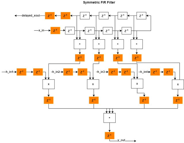
After code generation completes, the report shows four cycles of latency per output port, indicating that adaptive pipelining adds pipeline delays in the design. The post-implementation results show a positive slack of 0.146 ns, indicating that timing constraints are now met. The clock frequency is 206 MHz, above the 200 MHz target. These results were obtained by using MATLAB R2026b and Xilinx Vivado 2025.1.
This figure shows the hardware implementation of the algorithm with adaptive pipelining enabled. The additional delays from adaptive pipelining and delay balancing are shown in orange, along with the original input and output pipelines.
Limitations
Multiply operations might not be pipelined when adaptive pipelining is enabled if:
The multiply operation is in a
forloop that is not unrolled.The multiply operation is in a subfunction and
GenerateInstantiableCodeis not enabled.The multiply operation is in a subfunction and the function contains
coder.inline("never").

