Generate and Synthesize HDL Code for Symmetric FIR Filter Using the HDL Workflow Advisor
R2026bThis example shows you how to create an HDL Coder™ project and use the MATLAB HDL Workflow Advisor to generate code from a MATLAB® design, verify the MATLAB design with an HDL test bench, and synthesize the generated HDL code. This example uses ModelSim® as the HDL simulation tool and AMD® Vivado® as the third-party synthesis tool. For more information on generating HDL code and performing FPGA synthesis programmatically, see Programmatically Generate, Verify, and Synthesize HDL Code from MATLAB Code.
Examine the MATLAB Design
The MATLAB design mlhdlc_sfir is a simple symmetric FIR filter. Open the MATLAB design.
design_name = "mlhdlc_sfir";
testbench_name = "mlhdlc_sfir_tb";
evalc('open(design_name)');
Examine the MATLAB Test Bench
The mlhdlc_sfir_tb test bench defines low-pass filter coefficients and applies a representative input range. The test bench runs the design with these inputs to test the filter response. For more information on MATLAB test bench requirements and best practices, see Using Test Benches With HDL and HLS Code Generation.
Open the test bench.
evalc('open(testbench_name)');
Test the MATLAB Design
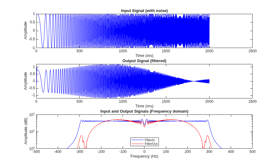
Verify that mlhdlc_sfir processes a sample stream without error and meets filtering requirements before generating HDL code. Run the design with mlhdlc_sfir_tb to produce a chirp input and provide low-pass filter coefficients. The test bench streams samples to mlhdlc_sfir, then plots the time- and frequency-domain behavior of the input and output signals.
The comparison plot shows that the filtered output is smoother than the input in the time domain. In the frequency domain, the magnitude of the filtered output is lower than the input at higher frequencies. The test bench results confirm mlhdlc_sfir implements a low-pass filter as expected according to the filter coefficients.
mlhdlc_sfir_tb
Set Up the Third-Party Synthesis Tool and HDL Simulator
Next, set up your third-party synthesis tool and HDL simulator. For a list of supported third-party tool versions, see HDL Language Support and Supported Third-Party Tools and Hardware.
This example uses AMD Vivado. To set the path to the third-party synthesis tool, use the hdlsetuptoolpath function. In the MATLAB Command Window, use this command, and replace the path with your installation path:
hdlsetuptoolpath("ToolName","Xilinx Vivado","ToolPath",...
               vivadopath);
To check your AMD Vivado synthesis tool setup, launch AMD Vivado by running this command:
!vivado
To simulate the generated HDL code using an HDL test bench, use an HDL simulator, such as ModelSim®. For more information on setting up third-party FPGA synthesis tools and HDL simulators, see Set Up Tools.
Note
Do not use spaces in file names or paths to prevent code generation failures. You can use the workDir name-value argument of the openExample function to open this example in a directory with a shorter name and no spaces or special characters. For example, this code sets the current working directory as your temporary folder directory for your system and opens the example.
tempdir
openExample("hdlcoder/BasicHDLCodeGenAndFPGASynthesisFromMATLABExample",workDir=tempdir)
Create an HDL Coder Project
To create an HDL Coder project:
1. In the MATLAB Command Window, create an HDL Coder project and open the HDL Workflow Advisor by running this command:
coder -hdlcoder -new sfir_project
2. In the HDL Workflow Advisor, in the Define Input Types task, for the MATLAB Function parameter, click Browse to browse to the MATLAB function, mlhdlc_sfir. Click Open to add the MATLAB function file to the project. Add only the top-level MATLAB function.
3. For the MATLAB Test Bench parameter, click the + button to browse to the MATLAB test bench mlhdlc_sfir_tb. Click Open to add the MATLAB test bench file to the project.
4. Click the Run button. The HDL Workflow Advisor runs the test bench to infer the input data types of the MATLAB design mlhdlc_sfir.
Create a Fixed-Point Version of the MATLAB Design
Next, convert floating-point data types in the MATLAB design to fixed-point data types by proposing fixed-point fraction lengths and adding a safety margin.
In the Fixed-Point Conversion task, click the Analyze Design button to generate an instrumented MEX function for data type range analysis.
You can use the Default word length property to specify the word lengths for floating-point data types. For this example, click Type proposal settings, then set the Default word length to 14.
To add a safety margin to the simulation-derived ranges and base fixed-point data type proposals on the expanded range, use the Safety margin for sim min/max (%) property. For this example, click Advanced, then set Safety margin for sim min/max (%) to 10.
Right-click the Fixed-Point Conversion task and select Run this task.
For more information on floating-point to fixed-point conversion, see Floating-Point to Fixed-Point Conversion.
Define Code Generation Target and Platform
To deploy generated HDL code on a target platform, specify the target and third-party synthesis tool before you generate HDL code.
In the Select Code Generation Target task, set these parameters:
Set Workflow to
Generic ASIC/FPGA.Set Synthesis tool to
Xilinx Vivado. If you do not see the synthesis tool, click Refresh list.Set Target frequency (MHz) to
200.
When you set Synthesis tool to Xilinx Vivado, the HDL Workflow Advisor exposes these properties and sets them to these settings:
The Chip family is set to
Artix UltraScale+.The Device is set to
xaau7p-fcva289-1-i.
Right-click the Select Code Generation Target task and select Run this task.
Set Code Generation Options and Generate HDL Code
Next, set HDL code generation options and generate code. In the HDL Code Generation task, set these options.
To generate Verilog code, in the Target tab, set Language to Verilog.
To generate a code generation report with comments and traceability links:
In the Target tab, select Generate report.
In the Coding Style tab, select Include MATLAB source code as comments.
To optimize your design by using distributed pipelining:
In the Optimizations tab, set Input pipelining and Output pipelining to
1.In the Optimizations tab, select Distribute pipeline registers.
To learn more about distributed pipelining optimization, see Specify Distributed Pipelining Settings.
Click Run.
After you generate the Verilog code, in the bottom of the right pane, click the View report link to open the HDL code generation report in the HDL Coder Report Viewer. For more information on HDL code generation reports, see Code Generation Reports.
Generate an HDL Test Bench and Simulate the Generated Code
Next, generate an HDL test bench, run the HDL test bench using an HDL simulator, and verify whether the HDL simulation matches the numerics and latency of the fixed-point MATLAB simulation. For more information on verifying generated HDL code with an HDL test bench, see Verify Code with HDL Test Bench.
In the Verify with HDL Test Bench task:
In the Output Settings tab, select Generate test bench.
Select Simulate generated test bench.
Set Simulation tool to
ModelSim.To generate the HDL test bench code and test bench data in separate files, in the Test Bench Options tab, select Multi file test bench.
Click Run.
Synthesize Generated HDL Code
Next, use HDL Coder to facilitate the synthesis of the generated HDL code on the target platform and generate area and timing reports for your design based on the target device.
To synthesize the generated HDL code:
1. Right-click the Synthesis and Analysis > Create Project task and select Run this task.
This task creates a Xilinx Vivado synthesis project for the HDL code. Xilinx Vivado uses this project to synthesize the design.
2. Right-click the Synthesis and Analysis > Run Synthesis task and select Run this task.
This task launches the synthesis tool in the background, opens the synthesis project, compiles the HDL code, synthesizes the design, and generates the netlists and area and timing reports.
3. Right-click the Synthesis and Analysis > Run Implementation task and select Run this task.
This task launches the synthesis tool in the background, runs place and route on the design, and generates pre- and post-route timing information for use in critical path analysis and back annotation of your source design.

