Complementary Filter
Libraries:
Sensor Fusion and Tracking Toolbox /
Multisensor Positioning /
Navigation Filters
Navigation Toolbox /
Multisensor Positioning /
Navigation Filters
Description
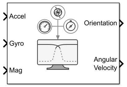
The Complementary Filter Simulink® block fuses accelerometer, magnetometer, and gyroscope sensor data to estimate device orientation.
Ports
Input
Accelerometer readings in the sensor body coordinate system in m/s2, specified as an N-by-3 matrix of real numbers. N is the number of samples, and the each row is of the form [x y z].
Data Types: single | double
Gyroscope readings in the sensor body coordinate system in rad/s, specified as an N-by-3 matrix of real numbers. N is the number of samples, and the each row is of the form [x y z].
Data Types: single | double
Magnetometer readings in the sensor body coordinate system in µT, specified as an N-by-3 matrix of real numbers. N is the number of samples, and the each row is of the form [x y z].
Dependencies
To enable this input port, select the Enable Magnetometer
input parameter.
Data Types: single | double
Output
Orientation of the sensor body frame relative to the navigation frame, returned as
an M-by-4 matrix of real numbers or a
3-by-3-by-M array. Each row of the M-by-4
matrix represents the four components of a quaternion. Each
page of the 3-by-3-by-M array represents a 3-by-3 rotation
matrix.
The number of input samples, N, determines the output size, M.
The output format depends on the value of the Orientation format
parameter.
Data Types: single | double
Angular velocity, with gyroscope bias removed, in the sensor body coordinate system in rad/s, returned as an M-by-3 matrix of real numbers.
The number of input samples, N, determines the output size, M.
Data Types: single | double
Parameters
Specify the navigation reference frame as NED (North-East-Down)
or ENU (East-North-Up).
Specify the format in which to output Orientation as
quaternion or Rotation
matrix:
quaternion—Orientationoutputs an M-by-4 matrix of real numbers. Each row of the matrix represents the four components of aquaternion.Rotation matrix—Orientationoutputs a 3-by-3-by-M array, in which each page of the array is a 3-by-3 rotation matrix.
The number of input samples, N, determines the output size, M.
Specify the accelerometer gain as a real scalar in the range [0, 1]. The gain determines how much the block trust the accelerometer measurement over the gyroscope measurement for orientation estimation.
Example: 0.02
Data Types: single | double
Select this parameter to enable input of magnetometer readings at the Mag port.
Specify the magnetometer gain as a real scalar in the range [0, 1]. The gain determines how much the block trust the magnetometer measurement over the gyroscope measurement for orientation estimation.
Example: 0.02
Data Types: single | double
Select the type of simulation to run from these options:
Interpreted execution— Simulate the model using the MATLAB® interpreter. This option shortens startup time, but has a slower simulation speed thanCode generation. In this mode, you can debug the source code of the block.Code generation— Simulate the model using generated C code. The first time you run a simulation in this mode, Simulink generates C code for the block. Simulink reuses the C code for subsequent simulations, as long as the model does not change. This option requires additional startup time, but the speed of subsequent simulations is comparable toInterpreted execution.
Extended Capabilities
C/C++ Code Generation
Generate C and C++ code using Simulink® Coder™.
Version History
Introduced in R2023a
MATLAB Command
You clicked a link that corresponds to this MATLAB command:
Run the command by entering it in the MATLAB Command Window. Web browsers do not support MATLAB commands.
Select a Web Site
Choose a web site to get translated content where available and see local events and offers. Based on your location, we recommend that you select: .
You can also select a web site from the following list
How to Get Best Site Performance
Select the China site (in Chinese or English) for best site performance. Other MathWorks country sites are not optimized for visits from your location.
Americas
- América Latina (Español)
- Canada (English)
- United States (English)
Europe
- Belgium (English)
- Denmark (English)
- Deutschland (Deutsch)
- España (Español)
- Finland (English)
- France (Français)
- Ireland (English)
- Italia (Italiano)
- Luxembourg (English)
- Netherlands (English)
- Norway (English)
- Österreich (Deutsch)
- Portugal (English)
- Sweden (English)
- Switzerland
- United Kingdom (English)