Consider Modeling Semantics when Generating Code
Data Propagation
The first stage of code generation is compilation of the block diagram. This stage is analogous to that of a C or C++ program. The compiler carries out type checking and preprocessing. Similarly, the Simulink® engine verifies that input/output data types of block ports are consistent, line widths between blocks are of expected thickness, and the sample times of connecting blocks are consistent.
The Simulink engine propagates data from one block to the next along signal lines. The data propagated consists of
Data type
Line widths
Sample times
You can verify what data types a Simulink block supports by typing
at the MATLAB® prompt, or (from the documentation) clicking the command above.
The Simulink engine typically derives signal attributes from a source block. For example, the Inport block's parameters dialog box specifies the signal attributes for the block.

In this example, the Inport block has a port width of 3, a sample time of .01 seconds, the data type is double, and the signal is complex.
This figure shows the propagation of the signal attributes associated with the Inport block through a simple block diagram.

In this example, the Gain and Outport blocks inherit the attributes specified for the Inport block.
Sample Time Propagation
Inherited sample times in source blocks (for example, a root inport) can sometimes lead to unexpected and unintended sample time assignments. Since a block may specify an inherited sample time, information available at the outset is often insufficient to compile a block diagram completely.
In such cases, the Simulink engine propagates the known or assigned sample times to those blocks that have inherited sample times but that have not yet been assigned a sample time. Thus, the engine continues to fill in the blanks (the unknown sample times) until sample times have been assigned to as many blocks as possible. Blocks that still do not have a sample time are assigned a default sample time.
For a completely deterministic model (one where no sample times are set using the above rules), you should explicitly specify the sample times of your source blocks. Source blocks include root inport blocks and blocks without input ports. You do not have to set subsystem input port sample times. You might want to do so, however, when creating modular systems.
An unconnected input implicitly connects to ground. For ground blocks and ground
connections, the sample time is always constant
(inf).
All blocks have an inherited sample time (Ts = -1). They are assigned a sample time of (Tf - Ti)/50.
Blocks Whose Outputs Have Constant Values
When you display sample time colors, by default, Constant blocks appear magenta in color to indicate that the block outputs have constant values during simulation. Downstream blocks whose output values are also constant during simulation, such as Gain blocks, similarly appear magenta if they use an inherited sample time. The code generated for these blocks depends in part on the tunability of the block parameters.
If you set model configuration parameter Default parameter
behavior to Inlined, the block parameters are not
tunable in the generated code. Because the block outputs are constant, the code generator
eliminates the block code due to constant folding. If the code generator cannot fold the
code, or if you select settings to disable constant folding, the block code appears in the
model initialization function. The generated code is more efficient because it does not
compute the outputs of these blocks during execution.
However, if you configure a block or model so that the block parameters appear in the generated code as tunable variables, the code generator represents the blocks in a different way. Block parameters are tunable if, for example:
You set parameter Default parameter behavior to
Tunable. By default, numeric block parameters appear as tunable fields of a global parameter structure.You use a tunable parameter, such as a
Simulink.Parameterobject that uses a storage class other thanAuto, as the value of one or more numeric block parameters. These block parameters are tunable regardless of the setting that you choose for model configuration parameter Default parameter behavior.
If a block parameter is tunable, the generated code must compute the block outputs
during execution. Therefore, the block code appears in the model step
function. If the model uses multiple discrete rates, the block code appears in the output
function for the fastest downstream rate that uses the block outputs.
Latches for Subsystem Blocks
When an Inport block is the signal source for a triggered or function-call subsystem, you can use latch options to preserve input values while the subsystem executes. The Inport block latch options include:
| For | Use |
|---|---|
| Triggered subsystems | Latch input by delaying outside signal |
| Function-call subsystems | Latch input for feedback signals of function-call subsystem outputs |
When you select subsystem block parameter Latch input for feedback signals of function-call subsystem outputs for a function-call subsystem, the code generator
Preserves latches in generated code regardless of optimizations that might be set
Places the code for latches at the start of a subsystem's output/update function
For more information on these options, see the block description of Inport.
Block Execution Order
Once the Simulink engine compiles the block diagram, it creates a
model.rtwmodel.rtw
You cannot override this execution order by directly calling a block (in handwritten
code) in a model. For example, in the next figure the
disconnected_trigger model on the left has its trigger port connected
to ground, which can lead to the blocks inheriting a constant sample time. Calling the
trigger function, f(), directly from user code does not work. Instead,
you should use a function-call generator to specify the rate at which
f() should be executed, as shown in the
connected_trigger model on the right.

Instead of the function-call generator, you could use another block that can drive the trigger port. Then, you should call the model's main entry point to execute the trigger function.
For multirate models, a common use of the code generator is to generate code for individual models separately and then manually code the I/O between the generated code modules. This approach places the burden of data consistency between models on the developer of the models. Another approach is to let Simulink and the code generator maintain data consistency between rates and generate multirate code for use in a multitasking environment. The Rate Transition block is able to interface periodic and asynchronous signals. For a description of the Simulink Coder™ block libraries, see Asynchronous Events. For more information on multirate code generation, see Tasking Modes and Execution Order.
Algebraic Loops
Algebraic loops are circular dependencies between variables. This prevents the straightforward direct computation of their values. For example, in the case of a system of equations
x = y + 2y = -x
the values of x and y cannot be directly
computed.
To solve this, either repeatedly try potential solutions for x and
y (in an intelligent manner, for example, using gradient based search)
or “solve” the system of equations. In the previous example, solving the
system into an explicit form leads to
2x = 2y = -xx = 1y = -1
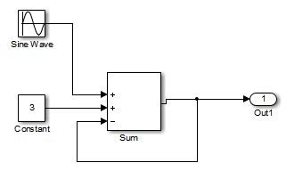
An algebraic loop exists whenever the output of a block having direct feedthrough (such as Gain, Sum, Product, and Transfer Fcn) is fed back as an input to the same block. The Simulink engine is often able to solve models that contain algebraic loops, such as the next diagram.

The code generator does not produce code that solves algebraic loops. This restriction includes models that use Algebraic Constraint blocks in feedback paths. However, the Simulink engine can often eliminate algebraic loops that arise, by grouping equations in certain ways in models that contain them. It does this by separating the update and output functions to avoid circular dependencies. For details, see Algebraic Loop Concepts.
Algebraic Loops in Triggered Subsystems
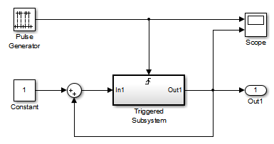
While the Simulink engine can minimize algebraic loops involving atomic and enabled subsystems, a special consideration applies to some triggered subsystems. An example for which code can be generated is shown in the following model and triggered subsystem.

The default Simulink behavior is to combine output and update methods for the subsystem, which creates an apparent algebraic loop, even though the Unit Delay block in the subsystem has no direct feedthrough.
You can allow the Simulink engine to solve the problem by splitting the output and update methods of triggered and enabled-triggered subsystems when feasible. If you want the code generator to take advantage of this feature, select subsystem block parameter Minimize algebraic loop occurrences. Select this parameter to avoid algebraic loop s in triggered subsystems involved in loops.
Note
If you check this box, the generated code for the subsystem might contain split output and update methods, even if the subsystem is not actually involved in a loop. Also, if a direct feedthrough block (such as a Gain block) is connected to the inport in the above triggered subsystem, the Simulink engine cannot solve the problem, and the code generator is unable to generate code.
A model configuration parameter Minimize algebraic loop occurrences is available also. Selecting it enables the code generator to produce code for models containing Model blocks that are involved in algebraic loops.