Convert Sample and Frame Rates in Simulink Using Frame Rebuffering Blocks
Frame Rebuffering Blocks
There are two common types of operations that impact the frame and sample rates of a signal: Frame rebuffering and direct rate conversion. Frame rebuffering, which is used to alter the frame size of a signal in order to improve simulation throughput, usually also changes either the sample rate or the frame rate of the signal. Direct rate conversions such as upsampling and downsampling can be implemented by altering either the frame rate or the frame size of a signal. For more details on the direct rate conversion technique, see Convert Sample and Frame Rates in Simulink Using Rate Conversion Blocks.
This topic contains two models that show how to change the sample rate of a signal using the frame rebuffering blocks. The following is a list of frame rebuffering blocks in DSP System Toolbox™.
Sometimes you might need to rebuffer a signal to a new frame size at some point in a model. For example, your data acquisition hardware may internally buffer the sampled signal to a frame size that is not optimal for the signal processing algorithm in the model. In this case, you can rebuffer the signal to a frame size more appropriate for the intended operations without introducing any change to the data or sample rate.
Blocks for Frame Rebuffering with Preservation of the Signal
Buffering operations provide another mechanism for rate changes in signal processing models. The purpose of many buffering operations is to adjust the frame size of the signal M without altering the sample rate of the signal Ts. This operation usually results in a change to the frame rate of the signal Tf according to the following equation:
However, this equation is true only if no samples are added to or deleted from the original signal. Therefore, this equation does not apply to buffering operations that generate overlapping frames, that only partially unbuffer frames, or that alter the data sequence by adding or deleting samples.
There are two blocks in the Buffers library that can be used to change a signal frame size without altering the signal itself:
The Buffer block preserves the signal data and sample
period only when its Buffer overlap parameter is set
to 0. The output frame period
Tfo is given by the
following equation:
where Tfi is the input frame period, Mi is the input frame size, and Mo is the output frame size specified by the Output buffer size (per channel) parameter.
The Unbuffer block unbuffers a frame signal and always preserves the signal data and sample period.
where Tfi and Mi are the period and size, respectively, of the frame signal.
Both the Buffer and Unbuffer blocks preserve the sample period of the sequence in the conversion (Tso = Tsi).
Blocks for Frame Rebuffering with Alteration of the Signal
Some forms of buffering alter the signal data or sample period in addition to adjusting the frame size. This type of buffering is desirable when you want to create sliding windows by overlapping consecutive frames of a signal, or when you want to select a subset of samples from each input frame for processing.
The following blocks alter a signal by adjusting its frame size. In this list, Tsi is the input sequence sample period, and Tfi and Tfo are the input and output frame periods, respectively:
Buffer –– The Buffer block adds duplicate samples to a sequence when the Buffer overlap parameter L is set to a nonzero value. The output frame period is related to the input sample period by the following equation:
where Mo is the output frame size specified by the Output buffer size (per channel) parameter. As a result, the new output sample period is
Delay Line –– The Delay Line block adds duplicate samples to the sequence when the Delay line size parameter Mo is greater than 1. The output and input frame periods are the same and equal the input sample period, Tfo = Tfi = Tsi. The new output sample period is:
Variable Selector –– The Variable Selector block can remove, add, and rearrange samples in the input frame when Select is set to
Rows. The output and input frame periods are the same, Tfo = Tfi, and the new output sample period is:where Mo is the length of the block output, determined by the Elements vector.
In all of these cases, the sample period of the output sequence is not equal to the sample period of the input sequence.
Buffer Signals by Preserving Sample Period
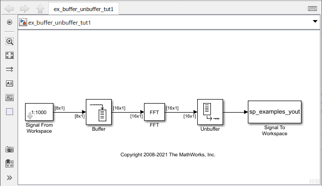
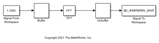
In this example, the Buffer block rebuffers the signal to a larger frame size. The Unbuffer block unbuffers the input frame into a sequence of scalar values.
A signal with a sample period of 0.125 seconds is rebuffered from a frame size of 8 to a frame size of 16. This rebuffering process doubles the frame period from 1 to 2 seconds, but does not change the sample period of the signal,  . The signal is then unbuffered into a sequence of sample outputs using the Unbuffer block. The frame period then changes to 0.125 seconds, which is equal to the value of the sample period of the signal.
This process does not add or delete samples from the original signal.
Open the model 'ex_buffer_tut1'.
The Signal From Workspace block has the Sample time parameter set to 0.125, and the Samples per frame parameter is set to 8. Each frame in the generated signal contains 8 samples and has a sample period of 0.125 seconds.
The Buffer block has the Output buffer size (per channel) parameter set to 16, and the Buffer overlap parameter is set to 0. The Buffer block rebuffers the signal from a frame size of 8 to a frame size of 16.
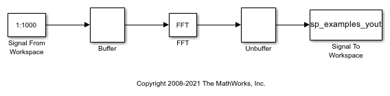
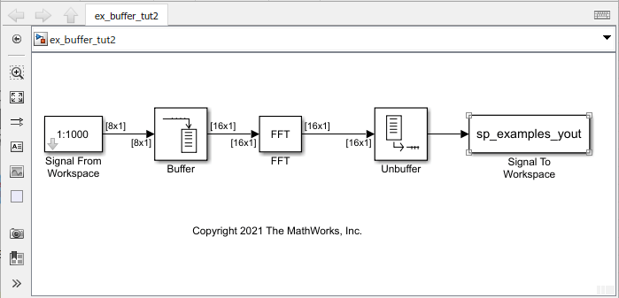
In the Debug tab, select Information Overlays > Signal Dimensions. When you run the model, the dimensions of the signals appear next to the lines connecting the blocks. The signal dimensions in the model confirm the following:
Buffer block changes the frame size of the signal from 8 to 16.
Unbuffer block unbuffers the signal into a sequence of scalar outputs.
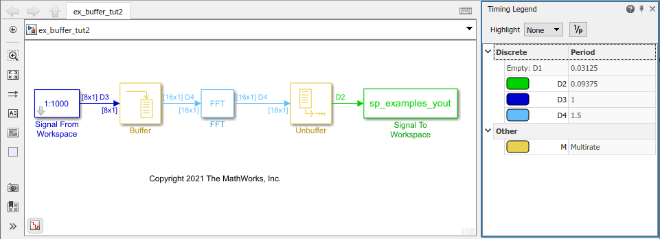
To view the effect on the frame period of the signal, enable color coding, annotations, and timing legend by selecting Information Overlays > Colors, Text, Timing Legend. In the Timing Legend, you can view the value of the frame period for each signal in the model, the color associated with the frame period, and the corresponding annotation.
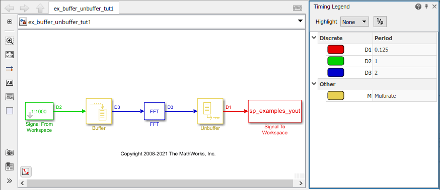
As you can see, the input frame period of the signal (denoted by D2 in the model), is given by  or
or  and equals 1 second. The Buffer block doubles the frame period from 1 to 2 seconds. The Unbuffer block that follows unbuffers the signal into a sequence of scalar outputs. The frame period of the unbuffered sequence equals 0.125 seconds, which matches the sample period of the signal.
Buffer Signals by Altering the Sample Period
In this example, the Buffer block rebuffers the signal to a larger frame size while overlapping 4 samples per frame.
Some forms of buffering alter the signal data or sample period in addition to adjusting the frame size. In the following example, a signal with a sample period of 0.125 seconds is rebuffered from a frame size of 8 to a frame size of 16 with a buffer overlap of 4 samples.
Open the model 'ex_buffer_tut2'.
The Signal From Workspace block has the Sample time parameter set to 0.125, and the Samples per frame parameter is set to 8. Each frame in the generated signal contains 8 samples and has a sample period of 0.125 seconds.
The Buffer block has the Output buffer size (per channel) parameter set to 16, and the Buffer overlap parameter is set to 4. The Buffer block rebuffers the signal from a frame size of 8 to a frame size of 16. After the initial output, the first four samples of each output frame are made up of the last four samples from the previous output frame.
In the Debug tab, select Information Overlays > Signal Dimensions. When you run the model, the dimensions of the signals appear next to the lines connecting the blocks. The signal dimensions in the model confirm the following:
Buffer block changes the frame size of the signal from 8 to 16.
Unbuffer block unbuffers the signal into a sequence of scalar outputs.
To view the effect on the frame period of the signal, enable color coding, annotations, and timing legend by selecting Information Overlays > Colors, Text, Timing Legend. In the Timing Legend, you can view the value of the frame period for each signal in the model, the color associated with the frame period, and the corresponding annotation.
Accounting for the overlap, the output frame period  of the Buffer block is given by the following equation:
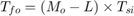
where  is the output frame size and equals 16,
  is the overlap and equals 4, and
  is the input sample period and equals 0.125 seconds. Substituting these values, the output frame period of the Buffer block becomes
  or
or  seconds. The corresponding sample period of the signal
  equals
  or
or  seconds. When you unbuffer the signal into a sequence of sample outputs, the frame period of the signal (shown as D2 in the model) matches the sample period value of 0.0938 seconds. Thus, both the data and the sample period of the signal have been altered by the buffering operation.