iirlp2bsc
Transform IIR lowpass filter to complex bandstop filter
Description
[
transform an IIR lowpass filter to a complex bandstop filter.num,den,allpassNum,allpassDen] =
iirlp2bsc(b,a,wo,wt)
The prototype lowpass filter is specified with the numerator
b and the denominator a. The function
returns the numerator and denominator coefficients of the transformed complex
bandstop filter. The function also returns the numerator,
allpassNum, and the denominator,
allpassDen, of the allpass mapping filter.
The function transforms a real lowpass prototype filter to a complex bandstop filter by applying a first-order real lowpass to complex bandstop frequency transformation. For more details, see IIR Lowpass Filter to IIR Complex Bandstop Filter Transformation.
Examples
Transform a lowpass IIR filter to a complex bandstop filter using the iirlp2bsc function.
Input Lowpass IIR Filter
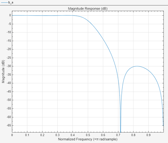
Design a prototype real IIR lowpass elliptic filter with a gain of about –3 dB at 0.5π rad/sample.
[b,a] = ellip(3,0.1,30,0.409);
filterAnalyzer(b,a)

Transform Filter Using iirlp2bsc
Transform the prototype lowpass filter into a complex bandstop filter by placing the cutoff frequencies of the prototype filter at –0.25π and 0.75π.
Specify the prototype filter as a vector of numerator and denominator coefficients, b and a respectively.
[num,den] = iirlp2bsc(b,a,0.5,[-0.25 0.75]);
Compare the magnitude response of the filters.
filterAnalyzer(b,a,num,den,FrequencyRange="centered",...
    FilterNames=["PrototypeFilter_TFForm",...
    "TransformedFilter"])

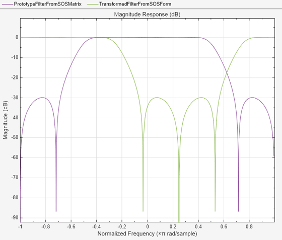
Alternatively, you can also specify the input lowpass IIR filter as a matrix of coefficients. Pass the second-order section coefficient matrices as inputs.
ss = tf2sos(b,a);
[num2,den2] = iirlp2bsc(ss(:,1:3),ss(:,4:6),0.5,[-0.25 0.75]);
Use the sos2ctf function to convert the second-order section matrices to the cascaded transfer function form.
[b_ctf,a_ctf] = sos2ctf(ss);
Compare the magnitude response of the filters.
filterAnalyzer(b_ctf,a_ctf,num2,den2,FrequencyRange="centered",...
    FilterNames=["PrototypeFilterFromSOSMatrix", ...
    "TransformedFilterFromSOSForm"])

Copyright 2012–2024 The MathWorks, Inc.
Input Arguments
Numerator coefficients of the prototype lowpass IIR filter, specified as either:
Row vector –– Specifies the values of [b0, b1, …, bn], given this transfer function form:
where n is the order of the filter.
Matrix –– Specifies the numerator coefficients in the form of an P-by-(Q+1) matrix, where P is the number of filter sections and Q is the order of each filter section. If Q = 2, the filter is a second-order section filter. For higher-order sections, make Q > 2.
In the transfer function form, the numerator coefficient matrix bik of the IIR filter can be represented using the following equation:
where,
a –– Denominator coefficients matrix. For more information on how to specify this matrix, see
a.k –– Row index.
i –– Column index.
When specified in the matrix form, b and a matrices must have the same number of rows (filter sections) Q.
Data Types: single | double
Complex Number Support: Yes
Denominator coefficients for a prototype lowpass IIR filter, specified as one of these options:
Row vector –– Specifies the values of [a0, a1, …, an], given this transfer function form:
where n is the order of the filter.
Matrix –– Specifies the denominator coefficients in the form of an P-by-(Q+1) matrix, where P is the number of filter sections and Q is the order of each filter section. If Q = 2, the filter is a second-order section filter. For higher-order sections, make Q > 2.
In the transfer function form, the denominator coefficient matrix aik of the IIR filter can be represented using the following equation:
where,
b –– Numerator coefficients matrix. For more information on how to specify this matrix, see
b.k –– Row index.
i –– Column index.
When specified in the matrix form, a and b matrices must have the same number of rows (filter sections) P.
Data Types: single | double
Complex Number Support: Yes
Frequency value to transform from the prototype filter, specified as a
scalar. Frequency wo should be normalized to be between
0 and 1, with 1
corresponding to half the sample rate.
Data Types: single | double
Desired frequency locations in the transformed target filter, specified as
a two-element vector. Frequencies in wt should be
normalized to be between -1 and 1,
with 1 corresponding to half the sample rate.
Data Types: single | double
Output Arguments
Numerator coefficients of the transformed complex bandstop filter, returned as one of the following:
Row vector of length n+1, where n is the order of the input filter. The
numoutput is a row vector when the input coefficientsbandaare row vectors.P-by-(Q+1) matrix, where P is the number of filter sections and Q is the order of each section of the transformed filter. The
numoutput is a matrix when the input coefficientsbandaare matrices.
Data Types: single | double
Complex Number Support: Yes
Denominator coefficients of the transformed complex bandstop filter, returned as one of the following:
Row vector of length n+1, where n is the order of the input filter. The
denoutput is a row vector when the input coefficientsbandaare row vectors.P-by-(Q+1) matrix, where P is the number of filter sections and Q is the order of each section of the transformed filter. The
denoutput is a matrix when the input coefficientsbandaare matrices.
Data Types: single | double
Complex Number Support: Yes
Numerator of the mapping filter, returned as a row vector.
Data Types: single | double
Complex Number Support: Yes
Denominator of the mapping filter, returned as a row vector.
Data Types: single | double
Complex Number Support: Yes
More About
IIR Lowpass Filter to IIR Complex Bandstop Filter transformation
effectively places one feature of the original filter, located at frequency
−wo, at the required target
frequency location, wt1, and the second
feature, originally at wo, at the new
location, wt2. It is assumed that
wt2 is greater than
wt1. Additionally, the
transformation swaps passbands with stopbands in the target filter.
Relative positions of other features of the original filter do not change in the target filter. This means that it is possible to select two features of an original filter, F1 and F2, with F1 preceding F2. Feature F1 will still precede F2 after the transformation. However, the distance between F1 and F2 will not be the same before and after the transformation.
Choice of the feature subject to the lowpass to bandstop transformation is not restricted only to the cutoff frequency of an original lowpass filter. You can choose to transform any feature of the original filter like stopband edge, DC, deep minimum in the stopband, or others.
Lowpass to bandpass transformation can also be used to transform other types of filters, for example. real notch filters or resonators can be doubled and positioned at two distinct desired frequencies at any place around the unit circle forming a pair of complex notches/resonators. This transformation can be used for designing bandstop filters for band attenuation or frequency equalizers, from the high-quality prototype lowpass filter.
Extended Capabilities
C/C++ Code Generation
Generate C and C++ code using MATLAB® Coder™.
Version History
Introduced in R2011a
MATLAB Command
You clicked a link that corresponds to this MATLAB command:
Run the command by entering it in the MATLAB Command Window. Web browsers do not support MATLAB commands.
Select a Web Site
Choose a web site to get translated content where available and see local events and offers. Based on your location, we recommend that you select: .
You can also select a web site from the following list
How to Get Best Site Performance
Select the China site (in Chinese or English) for best site performance. Other MathWorks country sites are not optimized for visits from your location.
Americas
- América Latina (Español)
- Canada (English)
- United States (English)
Europe
- Belgium (English)
- Denmark (English)
- Deutschland (Deutsch)
- España (Español)
- Finland (English)
- France (Français)
- Ireland (English)
- Italia (Italiano)
- Luxembourg (English)
- Netherlands (English)
- Norway (English)
- Österreich (Deutsch)
- Portugal (English)
- Sweden (English)
- Switzerland
- United Kingdom (English)