Spectrum Analysis of Signals in Simulink
This example shows you how to use Simulink® to undertake spectral analysis of signals. You can tune the radio to a band where a signal is present by changing the center frequency. You can then use the spectrum analyzer to view and make measurements on the received spectrum. You can either use recorded data from a file, or receive over-the-air signals in real time using an RTL-SDR radio, ADALM-PLUTO radio, or USRP™ radio.
The Spectrum Analysis of Signals example provides a MATLAB® implementation of this example.
Required Hardware and Software
By default, this example runs using recorded data from a file. Optionally, you can receive signals over-the-air. For this, you also need one of the following:
RTL-SDR radio and Communications Toolbox Support Package for RTL-SDR Radio.
Pluto radio and Communications Toolbox Support Package for Analog Devices® ADALM-PLUTO Radio.
USRP N2xx or B2xx series radio and Communications Toolbox Support Package for USRP Radio. For information on supported radios, see Supported Hardware and Required Software.
USRP E3xx, N3xx, X3xx, or X4xx series radio and Wireless Testbench Support Package for NI USRP Radios. For information on supported radios, see Supported Radio Devices (Wireless Testbench).
Overview
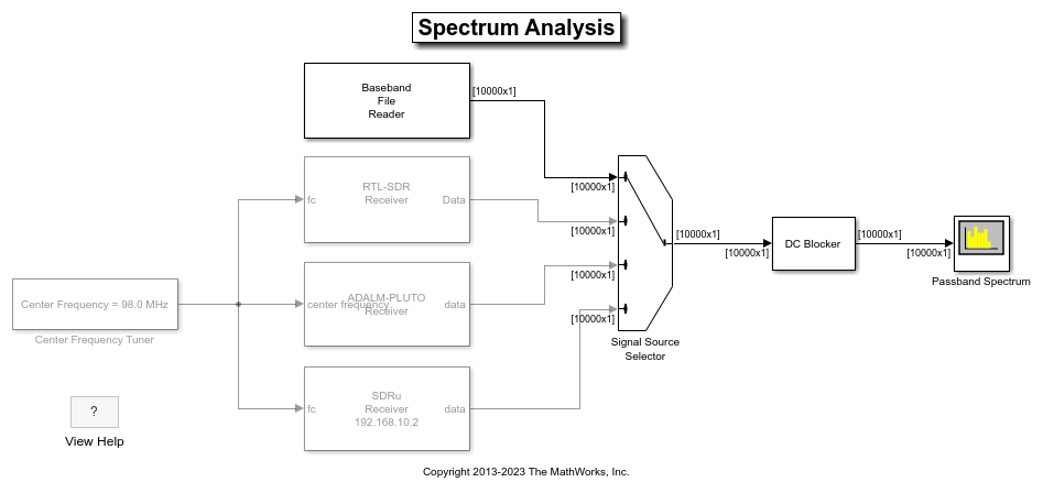
The spectralAnalysis model performs an FFT-based spectrum analysis at complex baseband, and provides:
A view of the spur-free dynamic range of the receiver
A view of the qualitative SNR level of the received signal
Structure of the Example
This figure shows the spectralAnalysis model:

Spectrum Analyzer
This figure shows the output of the Spectrum Analyzer for a data signal recorded in the spectrum_capture.bb file. The spectrum shows data captured over the FM radio band, specifically over the frequency range of 88 MHz to 108 MHz.

Running the Example
When you run the example, you can measure signal characteristics such as peaks, occupied bandwidth, adjacent channel power ratio, harmonic and intermodulation levels, and spur-free dynamic range.