winner2.AntennaArray
Create antenna array for WINNER II channel model
Description
Download Required: To use winner2.AntennaArray, first download the WINNER II Channel Model for Communications Toolbox add-on.
antArray = winner2.AntennaArray
antArray = winner2.AntennaArray( returns
a structure representing an antenna array defined using one or more Name,Value)Name,Value pair
arguments.
For more information, see Antenna Array Model.
Examples
Use the winner2.AntennaArray function to create an eight element uniform circular array (UCA-8) with a 1 cm radius.
UCA8 = winner2.AntennaArray('UCA',8,0.01);Plot element positions.
pos = {UCA8.Element(:).Pos};
plot(cellfun(@(x) x(1),pos),cellfun(@(x) x(2),pos),'+');
xlim([-0.02 0.02]); 
ylim([-0.02 0.02]);
title('UCA-8 Element Positions');
Use the winner2.AntennaArray function to create a two element uniform linear array (ULA-2) with 50 cm spacing and the dipole elements slanted at +45 and -45 degrees.
az = -180:179; % 1-degree spacing pattern = cat(1,shiftdim(winner2.dipole(az,45),-1), ... shiftdim(winner2.dipole(az,-45),-1)); ULA2 = winner2.AntennaArray('ULA',2,0.5, ... 'FP-ECS',pattern,'Azimuth',az);
Name-Value Arguments
Specify optional pairs of arguments as
      Name1=Value1,...,NameN=ValueN, where Name is
      the argument name and Value is the corresponding value.
      Name-value arguments must appear after other arguments, but the order of the
      pairs does not matter.
    
      Before R2021a, use commas to separate each name and value, and enclose 
      Name in quotes.
    
Example: Pos=[1 0 0; 0 1 0],'Rot',[0 0 0; 0 pi() 0] indicates the
                coordinates and rotation angles for two antenna elements.
Position of each antenna element, specified as an
                            NE-by-3 matrix. The three
                            columns represent the x-, y-, and z-coordinates in meters from the
                            origin. NE indicates the
                            number of elements in the antenna array. The elements have no rotation.
                            When there is more than one element, the 'Element'
                            field of antArray is a row vector of structures
                            representing all the elements.
Example: Pos=[63.1 10.2 11.5; 62 11 12] indicates the coordinates for two
                            antenna elements.
Data Types: double
Rotation angle of each antenna element, specified as an
                                NE-by-3 matrix. The three
                            columns represent the RotX,
                                RotY, and
                                RotZ rotation angles of
                            each antenna element in radians.
                                NE indicates the number of
                            elements in the antenna array. Rot only applies
                            when Pos is specified. If not specified with
                                Pos, the rotation angle is
                            0.
Example: Rot=[2 1.5 0; 0 pi() 0] indicates the rotation angles for two
                            antenna elements.
Data Types: double
Uniform circular antenna array, specified as N,Rad. In this argument,
                                N indicates the number of elements
                                (NE) and
                                Rad indicates the radius in meters. If
                                Rad is not specified, the default radius is 1
                            meter.
Example: UCA=8,0.5 indicates an eight element uniform circular array with
                            0.5 meter radius.
Data Types: double
Uniform linear antenna array, specified as N,Spacing. In this argument,
                                N indicates the number of elements
                                (NE) and
                                Spacing indicates the separation between adjacent
                            elements in meters. If Spacing is not specified, the
                            default separation is 1/N meters.
ULA elements are placed along x-axis with the center of the array at [0;0;0]. For an even number of elements, there is no antenna element at [0;0;0].
Example: ULA= [3,0.25] indicates a three element uniform linear array with
                            0.25 meter spacing between adjacent elements.
Data Types: double
Field pattern of element coordinate system, specified as a P-by-2-by1-by-NAZ array.
- The first dimension, P, can be either 1 or any number greater than or equal to the number of elements in the antenna array (NE). When P = 1, the same pattern applies to all elements. When P > NE, the first NE rows apply. 
- The second dimension, - 2, indicates that two polarizations characterize the field pattern. The first dimension in the field pattern stores vertical polarization, and the second one stores horizontal polarization.
- The third dimension, - 1, indicates that one elevation angle characterizes the field pattern.
- The fourth dimension, NAZ, is the number of field pattern samples taken between –180 and 180 degrees. NAZ equals the number of elements specified in - Azimuthor when- Azimuthis not present it equals the number of equidistant field pattern samples taken over azimuth angle.
Data Types: double
Field pattern array coordinate system, specified as a
                                P-by-2-by1-by-NAZ
                            array. Array format is the same as the FP-ECS
                            syntax, except that the field pattern is specified in the
                            array-coordinate-system (ACS).
- The first dimension, P, can be either 1 or any number greater than or equal to the number of elements in the antenna array (NE). When P = 1, the same pattern applies to all elements. When P > NE, the first NE rows apply. 
- The second dimension, - 2, indicates that two polarizations characterize the field pattern. The first dimension in the field pattern stores vertical polarization, and the second one stores horizontal polarization. Missing polarization dimensions of the field pattern are substituted with zeros.
- The third dimension, - 1, indicates that one elevation angle characterizes the field pattern.
- The fourth dimension, NAZ, is the number of field pattern samples taken between –180 and 180 degrees. NAZ equals the number of elements specified in - Azimuthor when- Azimuthis not present it equals the number of equidistant field pattern samples taken over azimuth angle.
Data Types: double
Azimuth angles for FP-ACS or FP-ECS field patterns
                            in degrees , specified as an
                                1-by-NAZ row vector. The
                            values in the row vector indicate azimuth angles for elements in the
                            field patterns.
Note
Azimuth applies only when
                                        FP-ACS or FP-ECS
                                    are defined. If Azimuth is not specified,
                                    uniform spacing is used for elements in the field
                                    pattern.
Example: Azimuth=[0 10 20 90 180 270 340 350]
Data Types: double
Output Arguments
Antenna array definition, returned as a structure containing these fields.
Antenna array name, returned as a character vector.
Antenna array position, returned as a 3-by-1 vector, representing the x-, y-, and z-coordinates in meters from the origin.
Antenna array rotation, returned as a 3-by-1 vector, representing the RotX, RotY, and RotZ rotation angles of each antenna element in radians.
Element definition, returned as a row vector of structures, with each structure representing one element and containing these fields.
Antenna array position, returned as a 3-by-1 vector, representing the x-, y-, and z-coordinates in meters from the origin.
Antenna array rotation, returned as a 3-by-1 vector, representing the RotX, RotY, and RotZ rotation angles of each antenna element in radians.
Aperture definition, returned as a structure representing the antenna aperture.
More About
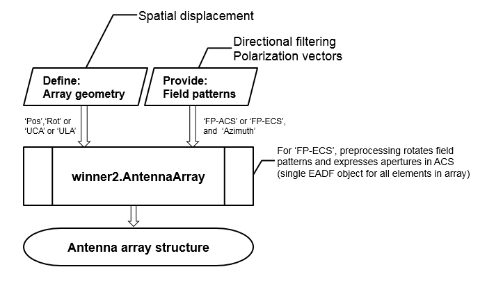
To create an antenna array model, you must
define the geometry of array elements (positions and rotation) and
the element field patterns. The arguments provided to winner2.AntennaArray are
always processed such that the array geometry is created first, and
then the field patterns are assigned.

For a detailed description of the antenna array specification for the WINNER channel model, see WINNER II Channel Models [1], Section 4.1.
References
[1] Kyosti, Pekka, Juha Meinila, et al. WINNER II Channel Models. D1.1.2 V1.2. IST-4-027756 WINNER II, September 2007.
Version History
Introduced in R2017a
See Also
MATLAB Command
You clicked a link that corresponds to this MATLAB command:
Run the command by entering it in the MATLAB Command Window. Web browsers do not support MATLAB commands.
Select a Web Site
Choose a web site to get translated content where available and see local events and offers. Based on your location, we recommend that you select: .
You can also select a web site from the following list
How to Get Best Site Performance
Select the China site (in Chinese or English) for best site performance. Other MathWorks country sites are not optimized for visits from your location.
Americas
- América Latina (Español)
- Canada (English)
- United States (English)
Europe
- Belgium (English)
- Denmark (English)
- Deutschland (Deutsch)
- España (Español)
- Finland (English)
- France (Français)
- Ireland (English)
- Italia (Italiano)
- Luxembourg (English)
- Netherlands (English)
- Norway (English)
- Österreich (Deutsch)
- Portugal (English)
- Sweden (English)
- Switzerland
- United Kingdom (English)