CPM Demodulator Baseband
Demodulate signal using CPM method and Viterbi algorithm
Libraries:
Communications Toolbox /
Modulation /
Digital Baseband Modulation /
CPM
Description
The CPM Demodulator Baseband block demodulates an input signal that was modulated using the continuous phase modulation (CPM) method. The input to this block is a baseband representation of the modulated signal. For more information about this demodulation and the filtering applied, see Algorithms.
Examples
Compute the bit error rate for a continuous phase modulated signal passed through an AWGN channel.
The cm_cpm_demod model passes a CPM-modulated signal through AWGN, demodulates the signal, and then computes the error rate of the received bits.
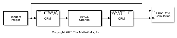
Run the model to compute the bit rate error.
BER = 0.002033
Number of errors = 2
Number of samples = 984
Ports
Input
CPM-modulated baseband signal, specified as a scalar or column vector. The length of the input signal must be an integer multiple of the number of samples per symbol specified in the Samples per symbol parameter. For information on the processing rates, see Single-Rate Processing and Multirate Processing.
This port is unnamed on the block.
Data Types: double | single
Output
Demodulated output signal, returned as a scalar or column vector. For more information, see Integer-Valued and Binary-Valued Output Signals and Traceback Depth and Output Delays.
This port is unnamed on the block.
Data Types: double | Boolean | int8 | int16 | int32
Parameters
To edit block parameters interactively, use the Property Inspector. From the Simulink® Toolstrip, on the Simulation tab, in the Prepare gallery, select Property Inspector.
Modulation order, specified as a power-of-two scalar. The modulation order M = 2k specifies the number of points in the symbol alphabet. k is a positive integer indicating the number of bits per symbol.
Integer or group of bits output indicator, specified as
Integer or Bit.
Set this parameter to
Integerto output data as integers.Set this parameter to
Bitto output data as bits.
For more information, see Integer-Valued and Binary-Valued Output Signals.
Symbol mapping of bit outputs, specified as Binary or
Gray. This parameter determines how each integer maps to a group
of output bits.
Set this parameter to
Binaryto map symbols using binary-coded ordering.Set this parameter to
Grayto map symbols using Gray-coded ordering.
For more information, see Integer-Valued and Binary-Valued Output Signals.
Dependencies
To enable this parameter, set Output type to Bit.
Modulation index {hi}, specified as a nonnegative scalar or column vector. The modulator operates in multi-h. For more information, see CPM Demodulation.
Type of pulse shaping used to smooth the phase transitions of the modulated signal,
specified as Rectangular, Raised Cosine,
Spectral Raised Cosine, Gaussian, or
Tamed FM. For more information on the filtering options, see Pulse Shape Filtering.
Main lobe duration of the largest lobe in the spectral raised cosine pulse, specified as a positive integer representing the number of symbol intervals used to pulse-shape the modulated signal.
Dependencies
To enable this parameter, set Frequency pulse shape to
Spectral Raised Cosine.
Rolloff factor of the spectral raised cosine pulse, specified as a scalar in the range [0, 1].
Dependencies
To enable this parameter, set Frequency pulse shape to
Spectral Raised Cosine.
Product of the bandwidth and symbol time of the Gaussian pulse shape, specified as a positive scalar. Use BT product to reduce the bandwidth, at the expense of increased intersymbol interference.
Dependencies
To enable this parameter, set Frequency pulse shape to
Gaussian.
Frequency pulse shape length, specified as a positive scalar. For more information on the frequency pulse length, refer to LT in Pulse Shape Filtering.
Data symbols used before the start of simulation, specified as scalar or vector with odd integer elements in the range [– (M – 1), (M – 1)]. M represents the modulation order, which is specified by the M-ary number parameter. The Symbol prehistory parameter defines the data symbols used by the modulator prior to the first call of the block, in reverse chronological order.
A scalar value expands to a vector of length LP – 1. LP represents the pulse length, which is specified by the Pulse length (symbol intervals) parameter.
For a vector, the length must be LP – 1.
Initial phase offset in radians, specified as a scalar. This property value is the initial phase offset of the modulated waveform.
Symbol sampling rate, specified as a positive integer. This parameter specifies the output symbol upsampling factor for each input sample.
For more information, see Signal Upsampling and Rate Changes.
Tip
To accurately model nonbinary pulse shapes, specifically pulse shapes other than rectangular, you should set the symbol sampling rate to values greater than 4.
Block processing rate, specified as one of these options:
Enforce single-rate processing— The input and output signals have the same port sample time. The block implements the rate change by making a size change at the output when compared to the input. The output width is the number of symbols (which is given by dividing the input length by the Samples per symbol parameter value when the Output type parameter is set toInteger).Allow multirate processing— The input and output signals have different port sample times. The output period is the same as the symbol period and equals the product of the input period and the Samples per symbol parameter value.
Traceback depth for the Viterbi algorithm, specified as a positive integer. The traceback depth specifies the number of trellis branches that the Viterbi algorithm uses to construct each traceback path. The value of this parameter is also the output delay and the number of zero symbols that precede the first meaningful demodulated symbol in the output. For more information, see Traceback Depth and Output Delays.
Output data type, specified as double,
boolean, int8,
int16, or int32.
When you set the Output type parameter to
false, you can set the output to double-precision or signed-integer data types.When you set the Output type parameter to
true, you can set the output to double-precision, signed-integer, or logical data types.
Block Characteristics
Data Types |
|
Multidimensional Signals |
|
Variable-Size Signals |
|
More About
When you set the Output type parameter to
Integer:
The block outputs an integer column vector of length equal to N/NSPS. The output values are odd integers in the range [–(M–1), (M–1)].
You cannot set the Output datatype parameter to
boolean.
When you set the Output type parameter to
Bit:
The block outputs a binary column vector of length equal to k×(N/NSPS).
In bit output mode, the block follows this process:
Map each demodulated symbol to an odd integer L in the range [–(M–1), (M–1)].
Map L to the nonnegative integer (L + M–1)/2.
Map each nonnegative integer to a k-length binary word using binary-coded ordering or Gray-coded ordering, as specified by the Symbol set ordering parameter.
You can set the Output datatype parameter to only
double,boolean,int8,in16, orint32.
N is the number of input baseband modulated symbols in the input signal (specifically, the length of the input signal). NSPS represents the value of the Samples per symbol parameter. M represents the value of the M-ary number parameter. k = log2(M) and k is the number of bits per symbol.
In single-rate processing mode, the input and output signals have the same port sample time. The block implicitly implements the rate change by making a size change at the output when compared to the input. The input width must be an integer multiple of the Samples per symbol parameter value, and the input can be a column vector.
When you set Output type to
Bit, the output width is k times the number of input symbols.When you set Output type to
Integer, the output width is the number of input symbols.
In multirate processing mode, the input and output signals have different port sample times. The input must be a scalar. The output symbol time is the product of the input sample time and the Samples per symbol parameter value.
When you set Output type to
Bit, the output width equals the number of bits per symbol.When you set Output type to
Integer, the output is a scalar.
The traceback depth, D, is the number of trellis branches used to construct each traceback path in the trellis description of the modulation scheme for demodulation using the Viterbi algorithm.
Determine the optimal setting for traceback depth by calculating the minimum squared Euclidean distance. Alternatively, you can use a common heuristic based on the number of states. Specifically, the five-times-the-constraint-length rule, which approximates the traceback depth as D=5log2(numStates).
For a binary raised cosine pulse shape with a pulse length of 3 and h=2/3, applying this rule D=5log2(3×22) ~ 18 gives a result that is close to the optimum value of 20.
The Viterbi algorithm processing results in a delay preceding the first meaningful demodulated value in the output.
The traceback depth equals the value of the Traceback depth parameter. The length of the delay vector is:
(D+1) zero-value symbols, when the Rate options parameter is set to
Allow multirate
        processing
and the model uses a variable-step solver or a fixed-step solver with the Tasking Mode parameter set toSingleTasking.D zero-value symbols, when the Rate options parameter is set to
Enforce single-rate processing.
Algorithms
CPM demodulation processing consists of a correlator followed by a maximum-likelihood sequence estimation (MLSE) detector that searches the paths through the state trellis for the minimum Euclidean distance path. When the modulation index is rational (h = m / p), a finite number of phase states exist in the symbol. The implementation uses the Viterbi algorithm to perform MLSE detection. The input to the demodulator is a baseband representation of the modulated signal.
{hi} is a sequence of modulation indices that moves cyclically through a set of indices {h0, h1, h2, …,hH-1}.
hi = mi / pi is the modulation index in proper rational form.
mi is the numerator of the modulation index.
pi is the denominator of the modulation index.
mi and pi are relatively prime positive numbers.
The least common multiple (LCM) of {p0, p1, p2, …,pH-1} is denoted as p.
hi= m'i / p.
{hi} determines the number of phase states,
and affects the number of trellis states,
numStates = numPhaseStates×M(L–1),
L is the pulse length.
M is the modulation order.
Continuous phase modulation includes a convolutional encoder, a symbol mapper, and a modulator.
The output of the modulator is a baseband representation of the modulated signal:
where:
{αi} is a sequence of M-ary data symbols selected from the alphabet ±1, ±3, ±(M–1).
M must have the form 2k for some positive integer k, where M is the modulation order and specifies the size of the symbol alphabet.
{hi} is a sequence of modulation indices. hi moves cyclically through a set of indices {h0, h1, h2, ..., hH-1}.
When H=1, only one modulation index exists, h0, which is denoted as h. The phase shift over a symbol is π × h.
When hi varies from interval to interval, the modulator operates in multi-h. To ensure a finite number of phase states, hi must be a rational number.
The CPM method uses pulse shaping to smooth the phase transitions of the modulated signal. The function q(t) is the phase response obtained from the frequency pulse, g(t), through this relation: .
The specified frequency pulse shape corresponds to these pulse shape expressions for g(t).
| Pulse Shape | Expression |
|---|---|
| Rectangular | |
| Raised cosine | |
| Spectral raised cosine | |
| Gaussian | |
| Tamed FM (tamed frequency modulation) |
Lmain is the main lobe pulse duration in symbol intervals.
β is the roll-off factor of the spectral raised cosine.
Bb is the product of the bandwidth and the Gaussian pulse.
The duration of the pulse, LT, is the pulse length in symbol intervals. As defined by the expressions, the spectral raised cosine, Gaussian, and tamed FM pulse shapes have infinite length. For all practical purposes, LT specifies the truncated finite length.
T is the symbol durations.
Q(t) is the complementary cumulative distribution function.
For more information on pulse shape filtering, see [1]
References
[1] Anderson, John B., Tor Aulin, and Carl-Erik Sundberg. Digital Phase Modulation. New York: Plenum Press, 1986.
[2] Proakis, John G. Digital Communications. 5th ed. New York: McGraw Hill, 2007.
Extended Capabilities
C/C++ Code Generation
Generate C and C++ code using Simulink® Coder™.
Version History
Introduced before R2006a
MATLAB Command
You clicked a link that corresponds to this MATLAB command:
Run the command by entering it in the MATLAB Command Window. Web browsers do not support MATLAB commands.
Select a Web Site
Choose a web site to get translated content where available and see local events and offers. Based on your location, we recommend that you select: .
You can also select a web site from the following list
How to Get Best Site Performance
Select the China site (in Chinese or English) for best site performance. Other MathWorks country sites are not optimized for visits from your location.
Americas
- América Latina (Español)
- Canada (English)
- United States (English)
Europe
- Belgium (English)
- Denmark (English)
- Deutschland (Deutsch)
- España (Español)
- Finland (English)
- France (Français)
- Ireland (English)
- Italia (Italiano)
- Luxembourg (English)
- Netherlands (English)
- Norway (English)
- Österreich (Deutsch)
- Portugal (English)
- Sweden (English)
- Switzerland
- United Kingdom (English)