Main Content

comm.OQPSKModulator

Modulation using OQPSK method

Description

The comm.OQPSKModulator object modulates the input signal using the offset quadrature phase shift keying (OQPSK) method and applies pulse shape filtering to the output waveform. For more information, see Pulse Shaping Filter. The output is a baseband representation of the modulated signal.

For information about delays incurred by modulator-demodulator pair processing, see Modulation Delays.

To modulate a signal using offset quadrature phase shift keying:

  1. Create the comm.OQPSKModulator object and set its properties.

  2. Call the object with arguments, as if it were a function.

To learn more about how System objects work, see What Are System Objects?

Creation

Description

oqpskmod = comm.OQPSKModulator creates a modulator System object™. This object applies offset quadrature phase shift keying (OQPSK) modulation and pulse shape filtering to the input signal.

example

oqpskmod = comm.OQPSKModulator(demod) creates a modulator System object with symmetric configuration to the OQPSK demodulator object, demod.

example

oqpskmod = comm.OQPSKModulator(Name,Value) sets properties using one or more name-value pairs. Enclose each property name in single quotes.

Example: comm.OQPSKModulator('BitInput',true)

oqpskmod = comm.OQPSKModulator(phase,Name,Value) sets the PhaseOffset property of the created object to phase and sets any other specified Name, Value pairs.

Example: comm.OQPSKModulator(0.5*pi,'SymbolMapping','Binary')

Properties

expand all

Unless otherwise indicated, properties are nontunable, which means you cannot change their values after calling the object. Objects lock when you call them, and the release function unlocks them.

If a property is tunable, you can change its value at any time.

For more information on changing property values, see System Design in MATLAB Using System Objects.

Phase offset from π/4, specified as a scalar in radians. The phase offset is applied to the zeroth point of the signal constellation before delay of quadrature component. After the OQPSK imaginary-component delay, the signal is normalized with unity power.

Example: 'PhaseOffset',pi/4 aligns the zeroth point of the QPSK signal constellation point on the axes, {(1,0), (0,j), (-1,0), (0,-j)}.

Data Types: double

Option to provide input in bits, specified as false or true.

  • When this property is set to false, the input values must be integer representations of two-bit input segments and range from 0 to 3.

  • When this property is set to true, the input must be a binary vector of even length. Element pairs are binary representations of integers.

Data Types: logical

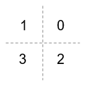
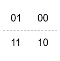
Signal constellation bit mapping, specified as 'Gray', 'Binary', or a custom 4-element numeric vector of integers with values from 0 to 3.

SettingConstellation Mapping for IntegersConstellation Mapping for BitsComment

Gray

Integer order Q1: 0, Q2: 1, Q3: 3, and Q4: 2

Bit order Q1: 00, Q2: 01, Q3: 11 and Q4: 10

The signal constellation mapping is Gray-encoded.

Binary

Integer order Q1: 0, Q2: 1, Q3: 2, and Q4: 3

Bit order Q1: 00, Q2: 01, Q3: 10 and Q4: 11

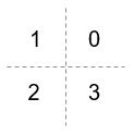
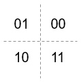
The signal constellation mapping for the input integer m (0 ≤ m ≤ 3) is the complex value e(j*(PhaseOffset+π/4) + j*2*π*m/4).

Custom 4-element numeric vector of integers with values from 0 to 3

Integer order Q1: a, Q2: b, Q3: c, and Q4: d

Bit order Q1: a, Q2: b, Q3: c, and Q4: d

Elements [a b c d] must be composed of the set of values [0, 1, 2, 3] in any order.

Data Types: char | double

Filtering pulse shape, specified as 'Half sine', 'Normal raised cosine', 'Root raised cosine', or 'Custom'.

Data Types: char

Raised cosine filter rolloff factor, specified as a scalar from 0 to 1.

Dependencies

This property is enabled when PulseShape is 'Normal raised cosine' or 'Root raised cosine'.

Data Types: double

Filter length in symbols, specified as a scalar. An ideal raised cosine filter has an infinite impulse response. However, to realize a practical implementation of this filter, the object truncates the impulse response to FilterSpanInSymbols symbols.

Dependencies

This property is enabled when PulseShape is 'Normal raised cosine' or 'Root raised cosine'.

Data Types: double

Custom filter numerator coefficients, specified as a row vector.

Dependencies

This property is enabled when PulseShape is 'Custom'.

Data Types: double
Complex Number Support: Yes

Custom filter denominator coefficients, specified as a row vector. When FilterDenominator is a scalar, the filter is FIR. When the FilterDenominator is not a scalar, the filter is IIR.

Dependencies

This property is enabled when PulseShape is 'Custom'.

Data Types: double
Complex Number Support: Yes

Number of samples per symbol, specified as a positive even integer.

Data Types: double

Data type assigned to output, specified as 'double' or 'single'.

Data Types: char

Usage

Description

example

waveform = oqpskmod(insignal) returns baseband-modulated output. The output waveform is pulse shaped according to the configuration properties PulseShape and SamplesPerSymbol.

Input Arguments

expand all

Input signal, specified as an NS-element column vector of integers or bits, where NS is the number of samples.

The setting of the BitInput property determines the interpretation of the input vector.

This object accepts variable-size inputs. After the object is locked, you can change the size of each input channel, but you cannot change the number of channels. For more information, see Variable-Size Signal Support with System Objects.

Data Types: double

Output Arguments

expand all

Output waveform, returned as a vector. The output waveform is pulse-shaped according to the configuration properties PulseShape and SamplesPerSymbol.

Object Functions

To use an object function, specify the System object as the first input argument. For example, to release system resources of a System object named obj, use this syntax:

release(obj)

expand all

constellationCalculate or plot ideal signal constellation

expand all

stepRun System object algorithm
releaseRelease resources and allow changes to System object property values and input characteristics
resetReset internal states of System object

Examples

collapse all

Create an OQPSK modulator and demodulator pair. Create an AWGN channel object having two bits per symbol.

oqpskmod = comm.OQPSKModulator('BitInput',true);
oqpskdemod = comm.OQPSKDemodulator('BitOutput',true);
channel = comm.AWGNChannel('EbNo',4,'BitsPerSymbol',2);

Create an error rate calculator. To account for the delay between the modulator and demodulator, set the ReceiveDelay property to 2.

errorRate = comm.ErrorRate('ReceiveDelay',2);

Process 300 frames of data looping through these steps.

  • Generate vectors with 100 elements of random binary data.

  • OQPSK-modulate the data. The data frames are processed as 50 sample frames of 2-bit binary data.

  • Pass the modulated data through the AWGN channel.

  • OQPSK-demodulate the data.

  • Collect error statistics on the frames of data.

for counter = 1:300
    txData = randi([0 1],100,1);
    modSig = oqpskmod(txData);
    rxSig = channel(modSig);
    rxData = oqpskdemod(rxSig);
    errorStats = errorRate(txData,rxData);
end

Display the error statistics.

ber = errorStats(1)
ber = 3.3336e-05
numErrors = errorStats(2)
numErrors = 1
numBits = errorStats(3)
numBits = 29998

Use an OQPSK demodulator object to initialize an OQPSK modulator object while creating it.

Create an OQPSK demodulator, assigning it a phase offset of 12π.

phase = 0.5*pi;
oqpskdemod = comm.OQPSKDemodulator(phase)
oqpskdemod = 
  comm.OQPSKDemodulator with properties:

   Modulation
         PhaseOffset: 1.5708
       SymbolMapping: 'Gray'
           BitOutput: false

   Filtering
          PulseShape: 'Half sine'
    SamplesPerSymbol: 4

      OutputDataType: 'double'

Use the demodulator object to initialize an OQPSK modulator while creating it.

oqpskmod = comm.OQPSKModulator(oqpskdemod)
oqpskmod = 
  comm.OQPSKModulator with properties:

   Modulation
         PhaseOffset: 1.5708
       SymbolMapping: 'Gray'
            BitInput: false

   Filtering
          PulseShape: 'Half sine'
    SamplesPerSymbol: 4

      OutputDataType: 'double'

Perform OQPSK modulation and demodulation and apply root raised cosine filtering to a waveform.

System initialization

Define simulation parameters and create objects for OQPSK modulation and demodulation.

sps = 12; % samples per symbol
bits = randi([0, 1], 800, 1); % transmission data

modulator = comm.OQPSKModulator( ...
    'BitInput',true, ...
    'SamplesPerSymbol',sps, ...
    'PulseShape','Root raised cosine');
demodulator = comm.OQPSKDemodulator(modulator);

Waveform transmission and reception

Use the modulator object to apply OQPSK modulation and transmit filtering to the input data.

oqpskWaveform = modulator(bits);

Pass the waveform through a channel.

snr = 0;
rxWaveform = awgn(oqpskWaveform,snr);

Use the demodulator object to apply receive filtering and OQPSK demodulation to the waveform.

demodData = demodulator(rxWaveform);

Compute the bit error rate to confirm the quality of the data recovery.

delay = (1+modulator.BitInput)*modulator.FilterSpanInSymbols;
[~, ber] = biterr(bits(1:end-delay), demodData(delay+1:end))
ber = 0

Use the qamdemod function to simulate soft decision output for OQPSK-modulated signals.

Generate an OQPSK modulated signal.

sps = 4;
msg = randi([0 1],1000,1);
oqpskMod = comm.OQPSKModulator( ...
    SamplesPerSymbol=sps, ...
    BitInput=true);
oqpskSig = oqpskMod(msg);

Add noise to the generated signal.

impairedSig = awgn(oqpskSig,15);

Perform Soft-Decision Demodulation

Create QPSK equivalent signal to align in-phase and quadrature.

impairedQPSK = complex( ...
    real(impairedSig(1+sps/2:end-sps/2)), ...
    imag(impairedSig(sps+1:end)));

Apply matched filtering to the received OQPSK signal.

halfSinePulse = sin(0:pi/sps:(sps)*pi/sps);
matchedFilter = dsp.FIRDecimator(sps,halfSinePulse, ...
    DecimationOffset=sps/2);
filteredQPSK = matchedFilter(impairedQPSK);

To perform soft demodulation of the filtered OQPSK signal use the qamdemod function. Align symbol mapping of qamdemod with the symbol mapping used by the comm.OQPSKModulator, then demodulate the signal.

oqpskModSymbolMapping = [1 3 0 2];
demodulated = qamdemod(filteredQPSK,4,oqpskModSymbolMapping, ...
    OutputType='llr');

Create a message signal in integers.

symbols = randi([0, 3], 800, 1);
order = 6;
btProduct = 0.5;
[num, denom] = butter(order, btProduct);
oqpskMod = comm.OQPSKModulator(PulseShape="Custom", FilterNumerator=num, FilterDenominator=denom);

Generate the waveform.

waveform = oqpskMod(symbols);  % joint oqpsk modulation and filtering

More About

expand all

Extended Capabilities

Version History

Introduced in R2012a

expand all