Bluetooth LE IQ samples Coherency and Dynamic Range Tests
This example shows you how to perform Bluetooth® low energy (LE) radio frequency (RF) physical layer (PHY) receiver tests specific to in-phase quadrature samples coherency (IQC) and IQ samples dynamic range (IQDR) by using Bluetooth® Toolbox. The tests compute relative phase, reference phase deviation, and amplitudes of IQ samples at each antenna in an antenna array. This example also verifies whether these test measurement values are within the limits specified by the Bluetooth RF-PHY Test Specification [3].
Objectives of Bluetooth RF-PHY Tests
The Bluetooth RF-PHY Test Specification [3] defined by the Bluetooth Special Interest Group (SIG) includes RF-PHY tests for transmitter and receiver. The objectives of these RF-PHY tests are to:
Ensure interoperability between all Bluetooth devices
Ensure a basic level of system performance for all Bluetooth products
Each test case has a specific test procedure and an expected outcome, which must be met by the implementation under test (IUT).
IQC and IQDR Tests
The Bluetooth Core Specification 5.1 [2] introduced angle of arrival (AoA) and angle of departure (AoD) direction finding features. For more information about direction finding services in Bluetooth LE, see Bluetooth LE Positioning by Using Direction Finding and Bluetooth Location and Direction Finding. The Bluetooth RF-PHY Test Specification [3] specifies the tests for direction finding transmitted waveforms with constant tone extension (CTE). This example includes AoA and AoD receiver tests specific to IQC and IQDR.
IQ sample coherency: This test verifies the relative phase and reference phase deviation values derived from the I and Q values sampled on AoA or AoD receiver.
IQ sample dynamic range: This test verifies the I and Q values sampled on AoA or AoD receiver by varying the dynamic range of the CTE.
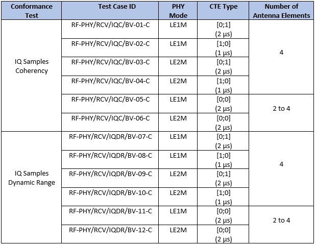
This table shows various RF-PHY AoA and AoD receiver tests performed in this example.
This block diagram summarizes the test procedure for IQC and IQDR test.
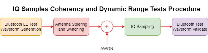
To simulate the IQC and IQDR tests, perform these steps.
Generate a Bluetooth LE test packet waveform.
Perform antenna switching and waveform steering.
Add thermal noise.
Perform IQ sampling on the noisy waveform.
Perform demodulation, decoding, and IQC and IQDR test measurements using
bluetoothTestWaveformValidatefunction.
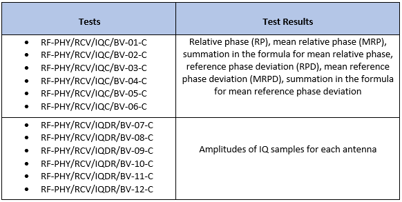
Based on the receiver test, the bluetoothTestWaveformValidate function returns these values.
Configure Simulation Parameters
Specify the test value as "IQ samples coherency" or "IQ samples dynamic range".
testValue =  "IQ samples coherency";
Specify the PHY transmission mode and CTE type.
phyMode ="LE2M"; cteType =
[1;0];
Specify the array size as 4 or [2 2] for AoD receiver tests and 2, 3, 4, or [2 2] for AoA receiver tests.
arraySize =  4;
4;Specify the samples per symbol. Set this value greater than 1.
sps = 8;
Specify the normalized spacing between the antenna elements with respect to the wavelength.
elementSpacing = 0.5;
Specify the length of frequency pulse shape in the range [1, 4].
pulseLength =  2;
2;Specify the modulation index in the range [0.45, 0.55].
modulationIndex = 0.5;
0.5;For CTE-based RF-PHY tests, specify the packet type as "ConnectionCTE" since the position of CTEInfo field is same for both the LE test packet and data packet.
packetType = "ConnectionCTE";Configure the RF-PHY test configuration by using the bluetoothRFPHYTestConfig object. Set the CTE length to 20.
configObject = bluetoothRFPHYTestConfig(Mode=phyMode, ...
    Test=testValue, ...
    CTEType=cteType, ...
    ArraySize=arraySize, ...
    SamplesPerSymbol=sps, ...
    ElementSpacing=elementSpacing, ...
    PacketType=packetType, ...
    CTELength=20, ...
    PulseLength=pulseLength, ...
    ModulationIndex=modulationIndex);

if (testValue=="IQ samples dynamic range")
    configObject.WantedSignalLevel = [-52 -49 -57 -62];
end
Based on the PHY transmission mode, compute the sampling rate.
sampleRate = 1e6*(1+1*(phyMode=="LE2M"))*sps; % In Hz
Generate RF-PHY Test Parameters
Generate slot duration, test switching pattern, number of packets to transmit and input power to the receiver by using the generateTestParameters function.
[slotDuration, numPacket, switchingPattern, rxPower] = generateTestParameters(configObject);
Create and configure Bluetooth LE angle estimation configuration object.
angleEstCfg = bleAngleEstimateConfig(ArraySize=arraySize, ...
    SlotDuration=slotDuration, ...
    SwitchingPattern=switchingPattern, ...
    ElementSpacing=elementSpacing);
Specify the noise figure in dB.
NF = 12;
Create and configure comm.ThermalNoise System object™.
thermalNoise = comm.ThermalNoise(NoiseMethod="Noise figure", ...
    SampleRate=sampleRate, ...
    NoiseFigure=NF);
Initialize the number of outputs based on the test value.
numOutputs = 2 + 4*(testValue=="IQ samples coherency");
[iqcIQDROutputs,iqcIQDROutputsConc] = deal(cell(1,numOutputs));
Simulate IQ Coherency or Dynamic Range Tests
Generate a Bluetooth LE test waveform with empty payload. Set the payload type to any value since the payload length is zero.
bleTestWaveformConfig = bluetoothTestWaveformConfig(Mode=phyMode, ...
    PacketType=packetType, ...
    PayloadType=randsrc(1,1,1:7), ...
    PayloadLength=0, ...
    CTELength=20, ...
    SamplesPerSymbol=sps, ...
    PulseLength=pulseLength, ...
    ModulationIndex=modulationIndex);

bleTestWaveform = bluetoothTestWaveform(bleTestWaveformConfig);
Simulate each Bluetooth LE test waveform by steering the angle and switching between different antennas. Attenuate the steered waveform and add thermal noise. Validate the noisy waveform by using bluetoothTestWaveformValidate function.
for countPacket = 1:numPacket
    % Generate random angle(s) between -90 to 90 degrees
    angles = randsrc(2,1,-90:90);

    dfWaveform = helperBLESteerSwitchAntenna(bleTestWaveform, ...
        angles, configObject.Mode, configObject.SamplesPerSymbol,configObject.PacketType, ...
        bleTestWaveformConfig.PayloadLength,angleEstCfg);

    dfWaveformAtt = dfWaveform.*10.^(rxPower/20);

    noisyWaveform = thermalNoise(dfWaveformAtt);
Validate the noisy Bluetooth LE waveform by using the bluetoothTestWaveformValidate function.
    [iqcIQDROutputs{:}] = bluetoothTestWaveformValidate(noisyWaveform,configObject);

    % Concatenate the outputs over the number of packets
    for countOutputs = 1:numOutputs
        iqcIQDROutputsConc{countOutputs} = [iqcIQDROutputsConc{countOutputs}; iqcIQDROutputs{countOutputs}];
    end
end
Test Verdict
Verify whether the IQC and IQDR test measurements are within the specified limits and display the test verdict.
switch configObject.Test
    case "IQ samples coherency"
        % For each nonreference antenna, Am, where m is in the range [0,
        % number of antenna elements-1], used in the switching pattern, the
        % results of the summations in the formulae for MRP(m) and MRPD
        % must be nonzero
        disp ("Expected summations in the formulae for MRP(m) and MRPD must be non-zero.");
        if all(all(iqcIQDROutputsConc{2}~=0)) && all(iqcIQDROutputsConc{5}~=0)
            disp("Result: Pass");
        else
            disp("Result: Fail");
        end

        % For each nonreference antenna, Am, used in the switching pattern,
        % 95% of the values, v, in the set must be
        % -0.52<=principal(v-MRP(m))<=0.52
        mrpRep = kron(iqcIQDROutputsConc{3},ones(length(iqcIQDROutputsConc{1})/length(iqcIQDROutputsConc{3}),1));
        subMRP = iqcIQDROutputsConc{1} - mrpRep;
        if size(subMRP,2) == 3 && any(strcmp(configObject.TestID,["RF-PHY/RCV/IQC/BV-01-C", ...
                "RF-PHY/RCV/IQC/BV-03-C","RF-PHY/RCV/IQC/BV-05-C","RF-PHY/RCV/IQC/BV-06-C"]))
            subMRP(3:3:end,3) = 0;
        end
        subMRPPrincipal = helperBLEPrincipalAngle(subMRP);
        subMRPRange = sum(subMRPPrincipal<=0.52 & subMRPPrincipal>=-0.52);
        disp ("Expected 95% of the values v in the set RP(m) must meet -0.52<=principal(v-MRP(m))<=0.52.");
        if all(subMRPRange>0.95*length(subMRPPrincipal))
            disp("Result: Pass");
        else
            disp("Result: Fail");
        end

        % MRPD must be in the range -1.125 to 1.125
        disp ("Expected MRPD in the range [-1.125, 1.125] radians.");
        if all(iqcIQDROutputsConc{6}<=1.125) && all(iqcIQDROutputsConc{6}>=-1.125)
            disp("Result: Pass");
        else
            disp("Result: Fail");
        end

    case "IQ samples dynamic range"
        % The mean of amplitudes of IQ samples measured at each antenna
        % follows the equation mean(ANT3)<mean(ANT2)<mean(ANT0)<mean(ANT1)
        meanA1 = mean(iqcIQDROutputsConc{1});
        meanA = mean(iqcIQDROutputsConc{2});
        if isscalar(meanA)
            disp("The mean of amplitudes must follow mean(ANT0)<mean(ANT1).");
            conditionCheck = meanA1<meanA(1);
        elseif length(meanA) == 2
            disp("The mean of amplitudes must follow mean(ANT2)<mean(ANT0)<mean(ANT1).");
            conditionCheck = meanA1<meanA(1) && meanA1>meanA(2);
        else
            disp("The mean of amplitudes must follow mean(ANT3)<mean(ANT2)<mean(ANT0)<mean(ANT1).");
            conditionCheck = meanA1<meanA(1) && meanA1>meanA(2) && meanA(3)<meanA(2);
        end
        if conditionCheck
            disp("Result: Pass");
        else
            disp("Result: Fail");
        end
end
Expected summations in the formulae for MRP(m) and MRPD must be non-zero.
Result: Pass
Expected 95% of the values v in the set RP(m) must meet -0.52<=principal(v-MRP(m))<=0.52.
Result: Pass
Expected MRPD in the range [-1.125, 1.125] radians.
Result: Pass
This example demonstrates the Bluetooth LE receiver test measurements specific to IQC and IQDR test measurements. The simulation results verify that the computed test measurement values are within the limits specified by the Bluetooth RF-PHY Test Specifications [3].
Appendix
The example uses these helpers:
helperBLEPrincipalAngle— Compute principal angle in radianshelperBLESteerSwitchAntenna— Perform antenna steering and switchinghelperBLESwitchAntenna— Perform antenna switching
Selected Bibliography
Bluetooth Special Interest Group (SIG), Inc. “Bluetooth® Technology Website – The Official Website for the Bluetooth Wireless Technology. Get up to Date Specifications, News, and Development Info.” Accessed May 24, 2024. https://www.bluetooth.com/.
Bluetooth Special Interest Group (SIG), Inc. “Core Specification – Bluetooth® Technology Website.” Accessed May 24, 2024. https://www.bluetooth.com/specifications/specs/core-specification-5-3/.
Bluetooth Special Interest Group (SIG). “Bluetooth RF-PHY Test Specification”, RF-PHY.TS.5.1.0, Section 4.5. https://www.bluetooth.com
Local Functions
function [slotDuration, packetCount, switchingPattern, rxPower] = generateTestParameters(cfgFormat)

% Get the slot duration based on CTE type
slotDuration = 2^(~cfgFormat.CTEType(1));

% Get the packet count based on array size and slot duration
if  isscalar(cfgFormat.ArraySize) && cfgFormat.ArraySize == 2
    packetCount = 1250;
    if slotDuration == 1
        packetCount = 556;
    end
elseif cfgFormat.ArraySize == 3
    packetCount = 2500;
    if slotDuration == 1
        packetCount = 1112;
    end
else
    packetCount = 3334;
    if slotDuration == 1
        packetCount = 1667;
    end
end

% Get the switching pattern based on array size
if  isscalar(cfgFormat.ArraySize) && cfgFormat.ArraySize == 2
    switchingPattern = [1 2 1 1];
elseif cfgFormat.ArraySize == 3
    switchingPattern = [1 2 1 1 1 3 1 1];
else
    switchingPattern = [1 2 1 1 1 3 1 1 1 4 1 1];
end

% Specify the samples per symbol
sps = cfgFormat.SamplesPerSymbol;

% Get the input power to the receiver
if (cfgFormat.Test=="IQ samples coherency")
    rxPower = -97;                          % In dB
else
    rxPower4Ant = [-52 -49 -57 -62];        % In dB

    % Calculate the length of waveform till reference period
    phyFactor = (1+1*(cfgFormat.Mode=="LE2M"));
    preambleLen = 8*phyFactor;              % Preamble length
    accAddLen = 32;                         % Access address length
    guardLen = 4;                           % Guard length
    referencePeriodLen = 8;                 % Reference period length
    crcLen = 24;                            % CRC length
    headerLen = 24;                         % Header length
    antenna1SamplesLength = (preambleLen+accAddLen+headerLen+crcLen+(guardLen+referencePeriodLen)*phyFactor)*sps;
    switchSampleSlotDur = 2*sps*slotDuration*phyFactor;
    numSlots = 74/slotDuration;
    rxPowerAnt = rxPower4Ant(switchingPattern);
    repFactor = ceil(numSlots/length(rxPowerAnt))+1;
    rxPowerAnt = repmat(rxPowerAnt,1,repFactor);
    rxPowerAnt = rxPowerAnt(1:numSlots+1);
    rxPowerSS = kron(rxPowerAnt',ones(switchSampleSlotDur,1));
    rxPowerRefPower = repmat(rxPower4Ant(1),antenna1SamplesLength-switchSampleSlotDur,1);
    rxPower = [rxPowerRefPower;rxPowerSS];
end
end