Import and Analyze Custom 3-D Antenna Geometry
This example shows how to simulate a 3-D custom antenna geometry from an STL (stereolithography) file. An STL file is a tessellation of a structure in 3-D space using triangles. To simulate a 3-D custom antenna geometry, use the customAntennaStl object. This object allows you to simulate a custom 3-D geometry from an *.stl file.
Create customAntennaStl Object
Create a customAntennaStl object with FileName set to the name of STL file that you want to use.
c = customAntennaStl(FileName="antenna3D.stl")c =
customAntennaStl with properties:
FileName: "antenna3D.stl"
Units: 'm'
FeedLocation: []
AmplitudeTaper: 1
PhaseShift: 0
UseFileAsMesh: 0
Tilt: 0
TiltAxis: [1 0 0]
View STL Geometry
View the 3-D antenna geometry from the STL file.
figure
show(c)
title("STL Geometry")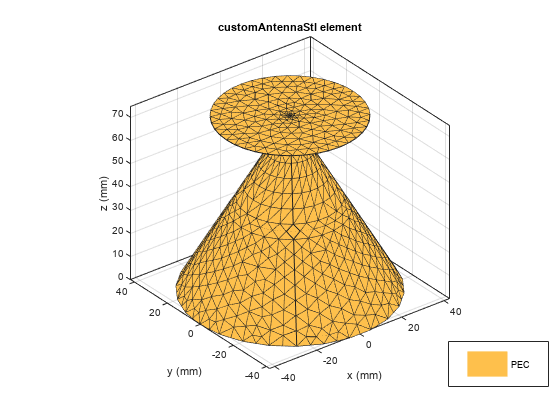
Create Feed
The STL file holds information about the 3-D geometry. However, It does not contain information about feeding edges or the feed location, Therefore, a feed is required to excite the antenna.
An antenna feed in customAntennaStl object can be created in two ways:
Create a feed using command line interface.
Create a feed using UI figure window which allows you to select the edges.
Create Feed Using Command Line Interface
To create a feed on the antenna, select an edge located at the origin at a height of 74.36 mm.
The edges are selected based on the distance between the feed location and the midpoints of the edges. The edges surrounding the feed are selected using NumEdges property.
In this example, the NumEdges property is set to 1. The closest single edge is selected as the feed.
c.createFeed('FeedLocation',[0,0,0.07436],NumEdges=1);View STL Geometry with Feed
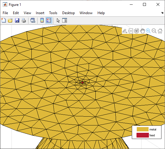
View the 3-D antenna geometry with feed. The feed is created at the specified FeedLocation.
figure
show(c)
title("STL Geometry with Feed Point")
Create Feed Using UI Figure Window
For complex 3-D antenna geometries, the feed could be set using UI figure window. To select the feeding edges, open the UI figure window using createFeed() function.
c.createFeed()
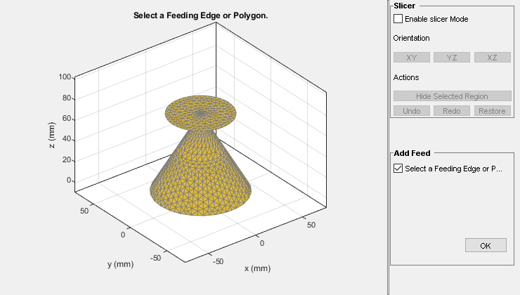
Select Slicer Mode
To select the feeding edge, the region of interest needs to be exposed in your 3-D structure where the feeding edge is located.
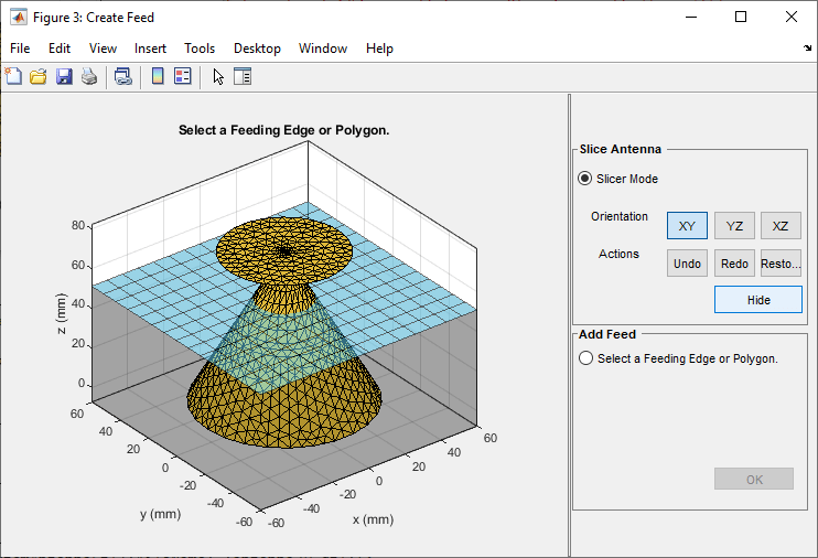
The UI figure window consists of two panes, the Slice Antenna pane and the Add Feed pane. The Slicer Mode when selected, creates a slicing plane that can be used to slice the 3-D structure. The orientation of the slicing plane can be shifted using the XY, YZ, and XZ buttons.
Select the Slicer Mode, then click XZ to select that as the plane along which to slice your antenna.

Select the region you want to hide.

Click Hide to hide the selected region. The selected region is grayed out.
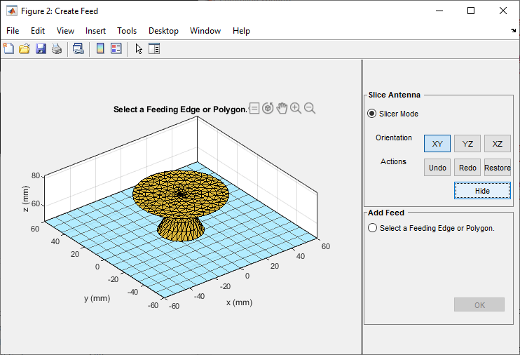
Repeat the process until you reach the region of interest.


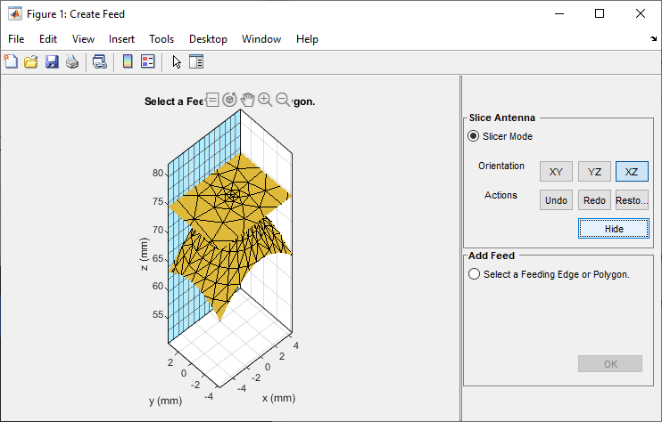
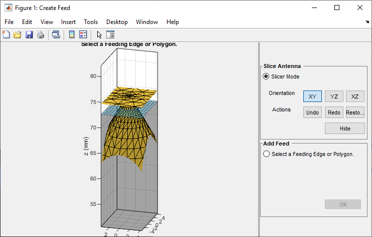

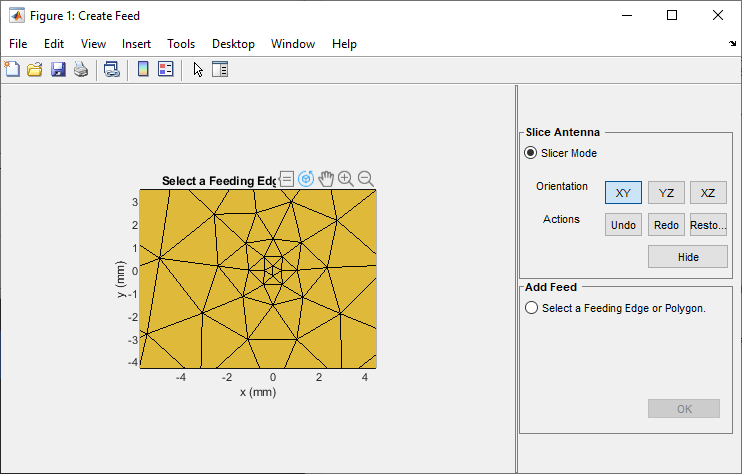
Use the Undo, Redo and Restore buttons to undo the changes created using hide option, redo the changes, and restore to the initial state, respectively.
Select Feeding Edge or Polygon
Select Select a Feeding Edge or Polygon in the Add Feed pane to select the desired feeding edge or feeding polygon. Click the edge to select it, and click it a second time to deselect it.
The feed can be created either selecting a single edge or selecting a group of edges that forms a polygon.
The image below shows how to select a feed as a single edge.

Select the edges that form a closed polygon.

The selected edges must be connected to other edges. If they are not, the UI figure window displays an error when you click OK.

In this example, the feed is created by selecting a polygon.
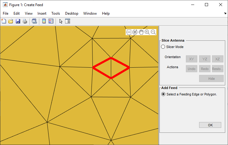
Click OK to define the selected edges as feeding edges and the structure with the feed is displayed.
figure
show(c)
title("STL Geometry with Feed")
The feed is created at the mean of all the points of the polygon.
Analyze Antenna
Analyze the antenna geometry using impedance and directivity plots.
figure
impedance(c,linspace(1.9e9,2.2e9,10))

The antenna structure resonates at 2.1 GHz. Plot the directivity of the antenna at resonant frequency.
figure
pattern(c,2.1e9)
