Finite Conductivity and Thickness Effect in MoM Solver
Antenna Toolbox™ uses the method of moments (MoM) computation technique for finite metal dielectric antennas. The MoM technique provides a computational solution to the electromagnetic problems by discretizing Maxwell's equations. The process results in this matrix-vector system:
where,
V — Applied voltage vector. This signal can be voltage or power applied to the antenna or an incident signal falling on the antenna.
I — Current vector that represents current on the antenna surface.
Z — Interaction matrix or impedance matrix that relates V to I. For more information on the interaction matrix, see Method of Moments Solver for Metal and Dielectric Structures.
In perfect electrically conducting (PEC) metals, the electrical conductivity is infinite, and the thickness is assumed to be infinitely thin. Therefore, the skin effect is not considered in PEC metal antenna. However, in most practical use metal antennas, the metal sheet has finite conductivity and finite thickness. This causes the formation of a finite skin depth effect that is commonly characterized by an equivalent surface impedance [1].
Antenna Toolbox uses the MoM [2] technique to solve finite metal antennas where the finite conductivity and thickness of the metal is considered through an equivalent surface. Thus, compared to PEC metal, there is no change in computational time and meshing in non-PEC metal antennas. The underlying electromagnetic theory of modelling finite conductor is explained below.
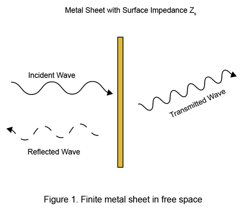
Consider a metal sheet with finite dimensions in free space as shown in Figure 1.
Using transmission line modelling, its equivalent circuit representation is modeled with equivalent surface impedance Zs. This is shown in Figure 2.

Finite conductivity poses a hindrance to the equivalent surface current flow on the antenna surface. Following the field continuity relation on the conductor surface, model the finite conductivity using an equivalent surface impedance. The equivalent surface impedance Zs can be written using [1] as
The parameter skin depth, physically signifies how much the surface current can penetrate the conducting surface. For PEC metals, the skin depth is zero as the conductivity is infinite. Thus, the entire current distribution lies over the surface layer in PEC metals. For non-PEC metals, if the skin depth value is very low, exp(kct) tends to be very high. In most practical use cases, the conductivity is very high and therefore, Z0 >> kc/σc. In such case Zs becomes:
If the thickness is high, exp(-2kct) tends to be negligible and Zs becomes:
Thus, for metals with high conductivity and thickness values, the surface impedance becomes independent of thickness.
MoM Formulation
In finite metal-dielectric structures, the elements of the metal-to-metal interaction matrix are computed as given in [2] and [3].
The first two terms in the equation consider the electric scalar potential and the magnetic vector potential of the electromagnetic fields. The third term considers the finite surface impedance effect due to the nonzero skin depth of the finite metal antennas. In PEC antennas, Zs = 0; thus, no finite conduction loss occurs in PEC metals. The Rao-Wilton-Glisson (RWG) [4] basis functions in MoM equation are used. For more information, see Method of Moments Solver for Metal and Dielectric Structures.
References
[1] A. Kerr. "Surface impedance of superconductors and normal conductors in EM simulators". MMA Memo, vol. 21, no. 245, pp. 1-17, 1999.
[2] Sarkar, T.K., and E. Arvas. “An Integral Equation Approach to the Analysis of Finite Microstrip Antennas: Volume/Surface Formulation.” IEEE Transactions on Antennas and Propagation 38, no. 3 (March 1990): 305–12. https://doi.org/10.1109/8.52238.
[3] Rengarajan, Sembiam Rajagopal, and Richard E. Hodges. “Accurate Evaluation of the Conductor Loss in Rectangular Microstrip Patch Reflectarrays”. Progress In Electromagnetics Research M 75 (2018): 159–66. https://doi.org/10.2528/PIERM18072606.
[4] Rao, S., D. Wilton, and A. Glisson. “Electromagnetic Scattering by Surfaces of Arbitrary Shape.” IEEE Transactions on Antennas and Propagation 30, no. 3 (May 1982): 409–18. https://doi.org/10.1109/TAP.1982.1142818.
See Also
Method of Moments Solver for Metal Structures | Method of Moments Solver for Metal and Dielectric Structures
Select a Web Site
Choose a web site to get translated content where available and see local events and offers. Based on your location, we recommend that you select: United States.
You can also select a web site from the following list
Americas
- América Latina (Español)
- Canada (English)
- United States (English)
Europe
- Belgium (English)
- Denmark (English)
- Deutschland (Deutsch)
- España (Español)
- Finland (English)
- France (Français)
- Ireland (English)
- Italia (Italiano)
- Luxembourg (English)
- Netherlands (English)
- Norway (English)
- Österreich (Deutsch)
- Portugal (English)
- Sweden (English)
- Switzerland
- United Kingdom (English)
Asia Pacific
- Australia (English)
- India (English)
- New Zealand (English)
- 中国
- 日本Japanese (日本語)
- 한국Korean (한국어)