doa
Description
[
calculates the direction of arrival of a signal when the transmission source is either a
single-feed antenna defined using a phiArrival,thetaArrival] = doa(obj,freq)conformalArray object or an incident
plane-wave defined using a planeWaveExcitation object.
Examples
Visualize a transmitter-receiver system as a conformal array. Use a conformalArray object with a dipole antenna as the transmitter element and an array of dipoles as the receiver element. Specify an operating frequency of 70 MHz.
f = 70e6;
lambda = 3e8/f;
Specify the location coordinates of the transmitter and the receiver.
txCenterOffset = [200,50,370];
rxCenterOffset = [0,0,0];
Create the first and second element of the conformal array.
elem1 = design(dipole,f);
elem1.Tilt = 90;
elem2 = linearArray(Element=elem1, NumElements=4, ElementSpacing=0.4*lambda);
Create and view the conformal array.
c = conformalArray;
c.Element = {elem1 elem2};
c.ElementPosition = [txCenterOffset; rxCenterOffset];
Calculate the direction of arrival.
[phiArrival,thetaArrival] = doa(c,f)
phiArrival =
14.0362
thetaArrival =
27.9882
Calculate the direction of arrival of a signal using the plane-wave excitation object. Use a linear array of dipoles operating at 2.4 GHz as the receiver element and set the azimuth and elevation reference angles.
azimuthRef = 10;
elevationRef = 30;
f = 2.4e9;
lambda = 3e8/f;
Design a dipole antenna using the specified frequency.
d = design(dipole,f);
d.Tilt = 90;
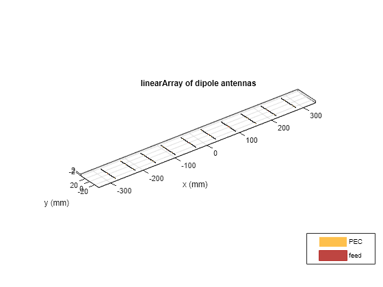
Create and view a linear array.
ant = linearArray(Element=d, NumElements=10, ElementSpacing=0.5*lambda);
show(ant)
Create a plane-wave excitation object using the dipole array.
dir = [sind(elevationRef)*cosd(azimuthRef) sind(elevationRef)*sind(azimuthRef) -cosd(elevationRef)];
pol = [cosd(elevationRef)*cosd(azimuthRef) cosd(elevationRef)*sind(azimuthRef) sind(elevationRef)];
pw = planeWaveExcitation(Element=ant, Direction=dir, Polarization=pol);
Calculate the direction of arrival.
[phiArrival,thetaArrival] = doa(pw,f)
phiArrival =
10
thetaArrival =
29.8900
Input Arguments
Output Arguments
Algorithms
To estimate the direction of arrival, the doa function uses the
fundamentals of RF propagation from the transmission to the reception of the signal. The phase
of a far-field received signal ER(r) at an
individual antenna is:
where β is the propagation constant of the received signal and r is the distance between the transmit and receive elements.
For a given transmit antenna, the position of the antenna element is [xtx, ytx, ztx], where
where ρ is the distance between the transmit element and the geometrical midpoint of the receive antenna array. θ is the elevation angle or the angular position of the transmit element from the z-axis and φ is the azimuth angle that lies in the xy-plane.
Assume that:
The receiver array is a homogenous linear or rectangular array with identical elements.
The separation between two adjacent elements of the receiver array is uniform. For a linear array, the element spacing is dspace. For a rectangular array, the row spacing is drow and the column spacing is dcol.
The receiver array has an equal number of elements along each axis. The number of elements along each axis of the array is even. For a linear array, the number of elements is Nelem. For a rectangular array, the number of elements in a row is Nrow and the number of elements in a column is Ncol.
For a uniform linear array (ULA) where the receive array elements lie along the x-axis, the position of the nth elements is
where Nelem is the number of elements in the ULA.
For the uniform rectangular array (URA), which lies in the xy-plane, the position of the receive array element in the nth row and mth column is [xposn yposn], where
Consider a single-antenna transmitter located at (xtx, ytx, ztx). This equation determines the far-field separation r between the receiver array element and the transmitter for a ULA:
.
This equation determines the far-field separation r between the transmitter and the element in the mth column and nth row of a URA:
The function uses these equations to calculate the phase of the electric field by doing a full-wave electromagnetic simulation and uses this phase to calculate the direction of arrival in terms of the elevation and azimuth angles.
Version History
Introduced in R2022a