CoaxialFeed
R2026bDescription
Use the CoaxialFeed object to specify the
FeedDefinitions property in a parent pcbStack
object.
The CoaxialFeed object models a coaxial-style feed as a signal via
excited across an annular antipad gap in a ground metal layer (higher-fidelity version of a
probe feed).
Creation
Description
f1 = CoaxialFeed creates a default
CoaxialFeed object.
f1 = CoaxialFeed( sets
object properties using one or more name-value arguments.
PropertyName=Value)PropertyName is the property name, and Value is
the corresponding value. You can specify several name-value arguments in any order as
PropertyName1=Value1,...,PropertyNameN=ValueN. Properties that you
do not specify retain their default values.
Properties
Examples
Define the radiating patch and the ground plane as two rectangles using the antenna.Rectangle object, with an air dielectric between them. Create the pcbStack object as a three-layer stack: the patch on the top layer, the dielectric in the middle, and the ground plane on the bottom layer.
r1 = antenna.Rectangle(Length=0.075, Width=0.0357);
r2 = antenna.Rectangle(Length=0.150, Width=0.0750);
d  = dielectric("Air");
p = pcbStack;
p.BoardShape = r2;
p.BoardThickness = d.Thickness;
p.Layers = {r1, d, r2};
To enable the FeedDefinitions property, set the FeedFormat property to FeedDefinitions.
p.FeedFormat = 'FeedDefinitions';Create two concentric circles at the feed site using the antenna.Circle object. The smaller circle defines the pad, the conductor shape that connects the probe to the board. The larger circle defines the antipad, the clearance ring that isolates the probe from the ground plane.
cPad = antenna.Circle(Center=[-0.0187 0], Radius=0.5e-3, NumPoints=16);
cAntipad = antenna.Circle(Center=[-0.0187 0], Radius=1.5e-3, NumPoints=16);
Etch the antipad clearance into the ground plane by subtracting the antipad shape, then restore the pad conductor by adding the pad shape back in. The ground plane is the third layer of the stack.
p.Layers{3} = p.Layers{3} - cAntipad + cPad;Create a CoaxialFeed object, using cPad and cAntipad for the PadShape and AntipadShape properties. The SignalLayers property connects the probe to the patch on layer 1, and the GroundLayers property references the ground plane on layer 3.
f = CoaxialFeed(PadShape=cPad, AntipadShape=cAntipad, ...
    SignalLayers=1, GroundLayers=3);
p.FeedDefinitions = f;
Display the structure to confirm the patch, the ground plane with its antipad gap, and the feed location.
figure
show(p)
title("Coaxial-fed Microstrip Patch Antenna")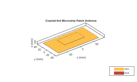
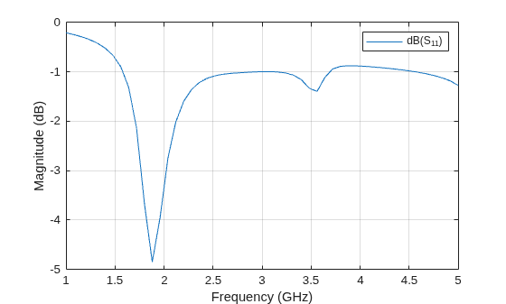
Then calculate and plot the reflection coefficient over a 1 GHz to 5 GHz frequency band.
s = sparameters(p, linspace(1e9, 5e9, 51));
figure
rfplot(s)
Version History
Introduced in R2026b

