Eaton Corporation Speeds Development of a Medium-Duty Hybrid Truck
“Using Simulink Real-Time enabled us to use inexpensive, readily available, off-the-shelf PC/104 CPU and I/O hardware. Without Simulink Real-Time, it would have been difficult to build and demonstrate this very flexible hybrid vehicle within the time and budget constraints that we had.”
Challenge
Solution
Results
- Inexpensive controller with flexible I/O
- Fast and easy development of control algorithms
- Easy tuning and download
Hybrid electric powertrains for trucks have the potential to reduce total cost and improve performance while also reducing emissions. They combine a traditional internal combustion engine, electric traction motors, a transmission, and energy storage devices that both propel the vehicle and extract and store energy during braking. The operation of these components is coordinated by a central powertrain control unit (PCU).
Eaton Corporation, a producer of powertrain components for trucks, designed a flexible, medium-duty, prototype hybrid truck, at the heart of which is a control unit designed with Simulink®, Stateflow®, and Simulink Real-Time™. Eaton also used Simulink Real-Time for hardware-in-the-loop (HIL) testing and deployment to ruggedized PC-compatible hardware. “Without Simulink Real-Time, it would have been difficult to build and demonstrate this very flexible hybrid vehicle within the time and budget constraints that we had,” says Richard Nellums, engineering manager – hybrid electric powertrain at Eaton.

Challenge
Designing and building a prototype hybrid vehicle is a significant challenge. The internal combustion engine, electric motor, transmission, and energy storage devices can be connected in several different configurations, depending on how the vehicle will be used, and these components need to be sized for optimal performance over various routes.
Designers will often use existing controllers if these provide enough I/O, throughput, and code space. For development purposes, however, prototype vehicles often have additional sensors, actuators, and I/O. Existing control code must be modified or rewritten to accommodate these requirements, and this can be a slow process. In addition, the control algorithms will typically be changed frequently, necessitating costly and time-consuming design iterations.
Eaton needed a controller that would adjust to quick changes to the control algorithms and an architecture that allowed for flexible configurations of the I/O. They also needed the capability to conduct test and design iterations quickly.

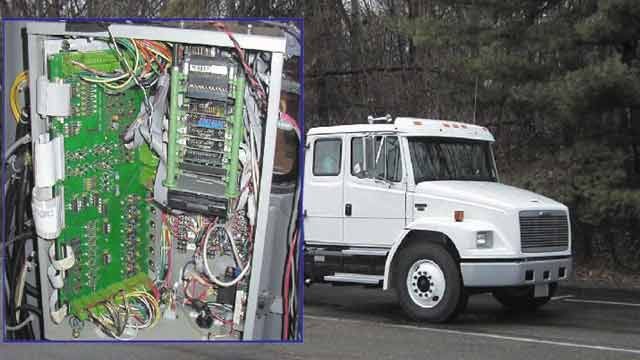
Powertrain control-system diagram with Simulink Real-Time I/O.
Solution
Eaton had been using Simulink, Stateflow, and Control System Toolbox™ for designing and simulating powertrain configurations and their control algorithms. Faced with a short timetable, a limited budget, and very diverse I/O requirements on the hybrid electric powertrain project, they chose to use these same tools and to use Simulink Real-Time to implement the controller. This provided them with the flexibility they needed to run iterative tests in a cost-effective way.
Dynamometer Testing
The Eaton engineers built, connected, and tested the powertrain components in phases. They modeled both the components and the tests using Simulink and then ran hardware-in-the-loop simulations by adding I/O blocks from Simulink Real-Time to the real hardware.
The electric motor and its DSP-based PCU were tested on a dynamometer under Simulink Real-Time control. This characterization of the motor helped in solving EMI (electromagnetic interference) problems that appeared due to the switching characteristics of the motor controller.
Because the hybrid powertrain was a prototype, Eaton also tested the entire system on an Simulink Real-Time controlled dynamometer. Simulink and Stateflow enabled them to generate and execute various standard test scenarios and they were able to operate and test all the components safely in the lab before road testing. Because Simulink Real-Time let them use readily available, inexpensive PC/104 CPU and I/O hardware, they were able to use multiple controllers. This expedited development by allowing multiple tests to be conducted simultaneously without a lot of effort in controller modification.
I/O Requirements
The Eaton hybrid truck powertrain contained a production diesel engine, an electric motor, and a transmission. The electronic controllers for each of these components communicated over CAN (J1939) links. The Simulink Real-Time PCU (the system controller) acted as a bridge between them, which necessitated the use of three separate CAN channels for the controller.
The driver indicators, driver controls, and other actuators and sensors required additional I/O. Simulink Real-Time enabled Eaton to meet these additional I/O requirements easily. For example, the off-the-shelf PC/104 I/0 boards provided 16 analog input channels, 8 analog output channels, 16 digital inputs, and 24 digital outputs, as well as frequency inputs and outputs and PWM (pulse width modulation) inputs and outputs. Only a little more than 50% of the I/O was used. The spare I/O and the ability to install additional I/O boards provided much-needed flexibility.
Installation
Eaton used a Simulink based controller model on the host for building and downloading to the Simulink Real-Time via an Ethernet connection. The Simulink Real-Time PC/104 stack consisted of a 400MHz CPU, an A/D board, an Ethernet card, a D/A board, two CAN boards, a timer/counter board, and a power supply board that converted the vehicle’s 12 volts of DC power to clean 5-volt power for the stack. A ruggedized LCD display was used as the target display. Simulink Real-Time read and updated the driver controller and display panel.
Running the Vehicle
Once the ignition switch was turned on, Simulink Real-Time controlled the vehicle using inputs from the driver. Simulink Real-Time ran control code generated, at the touch of a button, from Simulink Coder™. A state machine built with Stateflow ® blocks in the model determined the operation of the diesel engine, the electric motor, and other powertrain components. When it was running, the diesel engine was in override mode controlled by the CAN inputs received from Simulink Real-Time. Simulink Real-Time balanced the operation of the engine and the motor and achieved optimal operation of both of these prime movers.
Real-time data was captured using a host laptop computer from Simulink Real-Time and plotted using MATLAB. From this data and the real-time sounds and movements of the vehicle, the engineers could quickly analyze the performance of the PCU, modify the model, and build and download the modified code to Simulink Real-Time using Simulink Coder.
Using Simulink, Stateflow, Simulink Real-Time, a PC/104 to implement the PCU, and Simulink Coder to automatically generate and download the executable code to the target enabled Eaton to quickly obtain a controller that met the operational requirements for the prototype vehicle.
Results
- Inexpensive controller with flexible I/O. Simulink Real-Time and off-the-shelf I/O boards provided a low-cost PCU that is flexible and can be used with other powertrain configurations and for fleet installations.
- Fast and easy development of control algorithms. Simulink, Stateflow, and Control System Toolbox made modifying and sharing models and control algorithms between engineers quick and easy.
- Easy tuning and download. Simulink allowed for quick and easy in-vehicle tuning. The Eaton engineers could then download the code with the click of a button using Simulink Coder and Simulink Real-Time.