Configure Data Interface
About This Example
Learning Objectives
Configure the data interface for code generated for a model.
Control the name, data type, and data storage class of signals and parameters in generated code.
Prerequisites
Understanding ways to represent and use data and signals in models.
Familiarity with representing data constructs as data objects.
Ability to read C code.
Required Files
Model files ThrottleControlDataInterface and
ThrottleControlTestHarness
Declare Data
Most programming languages require that you declare data before using it. The declaration specifies the following information:
| Data Attribute | Description |
|---|---|
| Scope | The region of the program that has access to the data |
| Duration | The period during which the data is resident in memory |
| Data type | The amount of memory allocated for the data |
| Initialization | An initial value, a pointer to memory, or NULL. If you do not provide an initial value, most compilers assign a zero value or a null pointer. |
The following data types are supported for code generation.
Supported Data Types
| Name | Description |
|---|---|
double | Double-precision floating point |
single | Single-precision floating point |
int8 | Signed 8-bit integer |
uint8 | Unsigned 8-bit integer |
int16 | Signed 16-bit integer |
uint16 | Unsigned 16-bit integer |
int32 | Signed 32-bit integer |
uint32 | Unsigned 32-bit integer |
| Fixed-point data types | 8-, 16-, 32-bit word lengths |
A storage class is the scope and duration of a data item. For more information about storage classes, see C Data Code Interface Configuration for Model Interface Elements.
Use Data Objects
In Simulink® models and Stateflow® charts, the following methods are available for declaring data: data objects and direct specification. This example uses the data object method. Both methods allow full control over the data type and storage class. You can mix the two methods in a single model.
In the MATLAB® and Simulink environment, you can use data objects in various ways. This example focuses on the following types of data objects:
Signal
Parameter
Bus
To configure the data interface for your model using the data object method, in the MATLAB base workspace, you define data objects. Then, associate them with your Simulink model or embedded Stateflow chart. When you build your model, the build process uses the associated base workspace data objects in the generated code.
You can set the values of the data object properties, which include:
Data type
Storage class
Value (parameters)
Initial value (signals)
Identifier (define a different name in the generated code)
Dimension (typically inherited for parameters)
Complexity (inherited for parameters)
Unit (physical measurement unit)
Minimum value
Maximum value
Description (used to document your data objects — does not affect simulation or code generation)
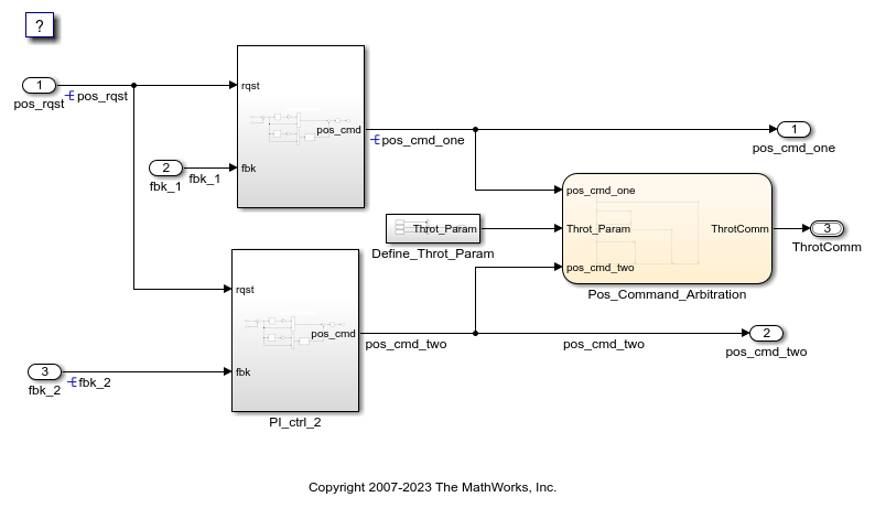
Open Example Model
Open the example model ThrottleControlDataInterface.
open_system('ThrottleControlDataInterface')
Explore Base Workspace Signal Data Objects
You can create and inspect base workspace data objects by entering commands in the MATLAB Command Window or by using Model Explorer. To explore base workspace signal data objects, use these steps:
Open Model Explorer.
Select Base Workspace.
Select the
pos_cmd_onesignal object for viewing.
You can also view the definition of a signal object. In the MATLAB Command Window, enter
pos_cmd_one:pos_cmd_one = Signal with properties: CoderInfo: [1x1 Simulink.CoderInfo] Description: 'Throttle position command from the first PI controller' DataType: 'double' Min: -1 Max: 1 Unit: '' Dimensions: -1 DimensionsMode: 'auto' Complexity: 'auto' SampleTime: -1 InitialValue: '0'To view other signal objects, in Model Explorer, click the object name or in the MATLAB Command Window, enter the object name. This table summarizes object characteristics for some of the data objects in this model.
Object Characteristics pos_cmd_onepos_rqstP_InErrMapThrotComm*ThrottleCommands*Description Top-level output Top-level input Calibration parameter Top-level output structure Bus definition Data type Double Double Auto Auto Structure Storage class Exported global Imported extern pointer Constant Exported global None *
ThrottleCommandsdefines a Bus object;ThrotCommis an instantiation of the bus. If the bus is a nonvirtual bus, the signal generates a structure in the C code.
You can use a bus definition (ThrottleCommands) to instantiate
multiple instances of the structure. In a model diagram, a bus object appears as a wide
line with central dashes, as shown.

Add New Data Objects
You can create data objects for named signals, states, and parameters. To associate a data object with a construct, the construct must have a name.
To find constructs for which you can create data objects, use the Data Object Wizard.
This tool finds the constructs and then creates the objects for you. The model includes two
signals that are not associated with data objects: fbk_1 and
pos_cmd_two.
To find the signals and create data objects for them:
In the Simulink Editor, in the Modeling tab, under Design, click Data Object Wizard. The Data Object Wizard dialog box opens.
To find candidate constructs, click Find. Constructs
fbk_1andpos_cmd_twoappear in the dialog box.To select both constructs, click Select All.
In the table, under Class, make sure that each proposed data object uses the class
Simulink.Signal. To change the class of the objects, click Change Class.To create the data objects, click Create. Constructs
fbk_1andpos_cmd_twoare removed from the dialog box.Close the Data Object Wizard.
In the Contents pane of the Model Explorer, find the newly created objects
fbk_1andpos_cmd_two.
Enable Data Objects for Generated Code
Enable a signal to appear in generated code.
In the Simulink Editor, right-click the
pos_cmd_onesignal line and select Properties. A Signal Properties dialog box opens.Make sure that you select the Signal name must resolve to Simulink signal object parameter.

Enable signal object resolution for the signals in the model. In the MATLAB Command Window, enter:
disableimplicitsignalresolution('ThrottleControlDataInterface')
Effects of Simulation on Data Typing
In the throttle controller model, the data types are set to double.
Because Simulink software uses the double data type for simulation, do not
expect changes in the model behavior when you run the generated code. You verify this
effect by running the test harness.
Before you run your test harness, update it to include the
ThrottleControlDataInterface model.
Note
The following procedure requires a Stateflow license.
Open your copy of test harness,
ThrottleControlTestHarness.Right-click the
Unit_Under_TestModel block and select Block Parameters (ModelReference).Set Model name to
ThrottleControlDataInterface. Click OK.Update the test harness model diagram.
Simulate the test harness.
The resulting plot shows that the difference between the golden and simulated versions of the model remains zero.

Manage Data
Data objects exist in a separate file from the model in the base workspace. To save the
data manually, in the MATLAB Command Window, enter save.
The separation of data from the model provides the following benefits:
One model, multiple data sets:
Use of different parameter values to change the behavior of the control algorithm (for example, for reusable components with different calibration values)
Use of different data types to change targeted hardware (for example, for floating-point and fixed-point targeted hardware)
Multiple models, one data set:
Sharing data between models in a system
Sharing data between projects (for example, transmission, engine, and wheel controllers can use the same CAN message data set)
Key Points
You can declare data in Simulink models and Stateflow charts by using data objects or direct specification.
From the Model Explorer or from the command line in the MATLAB Command Window, manage (create, view, configure, and so on) base workspace data.
The Data Object Wizard provides a quick way to create data objects for constructs such as signals, buses, and parameters.
Configure data objects explicitly to appear by name in generated code.
Separation of data from model provides several benefits.
Related Topics
You can also select a web site from the following list:
Americas
- América Latina (Español)
- Canada (English)
- United States (English)
Europe
- Belgium (English)
- Denmark (English)
- Deutschland (Deutsch)
- España (Español)
- Finland (English)
- France (Français)
- Ireland (English)
- Italia (Italiano)
- Luxembourg (English)
- Netherlands (English)
- Norway (English)
- Österreich (Deutsch)
- Portugal (English)
- Sweden (English)
- Switzerland
- United Kingdom (English)