Drilling Systems Modeling & Automation
Efforts are underway in the oil and gas industry to improve operations efficiency and cost through drilling systems automation. Recently, there has been a convergence of several technologies such as modeling algorithms, artificial intelligence and Internet of Things. This has created an opportunity to use models for design and testing of equipment. Combining physics-based models with data driven modeling techniques enables quicker overall product development time of rig systems as well as flexibility in optimizing the design parameters. These are also key to the concept of 'digital twin.'
This video series explores drilling systems modeling, with a focus on surface equipment including the drawworks, top drive, and mud pumps. We will demonstrate the following elements:
- Building a physics-based model and incorporating controls using pre-built blocks.
- Calibrating the model to the field data to create the digital twin using automated parameter estimation.
- Using the digital twin for optimizing system performance given operational constraints.
- Implementing state-based supervisory logic on the digital twin for testing control logic.
- Formal methods for verification, validation and testing of control logic against system requirements.
- Generating PLC and C++ code directly from the model. This code can be used for rapid prototyping, embedded code deployment or Hardware-in-the-loop (HIL) testing.
- Import existing PLC code for verification and testing.

Automate your drilling processes with Simulink
Use MATLAB & Simulink to build physics-based models of surface drilling equipment for digital twin applications and drilling systems automation.
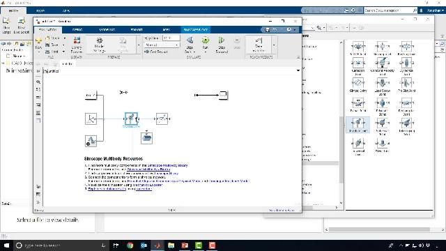
Introduction to Simulink and Simscape
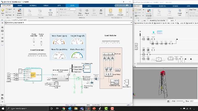
Simulink and Simscape are introduced by modeling the drawworks and mass assembly. SOLIDWORKS assemblies are imported into Simulink. Simscape Electrical is introduced by modeling in the electrical domain.

Validating model with field data
A digital twin of the surface drilling equipment is built by callibrating the models to field data.

Using simulation to optimize system performance
An optimized lookup table is built to allow operators to control the drawworks at the maximum speed given operational constraints. This is incorporated into the control logic to ensure operator limits.
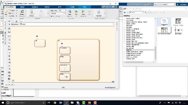
Auto driller logic is built that senses the mass & current position of the top drive and adjusts the motor speed setpoint dynamically. State-based supervisory control logic is built with Stateflow.
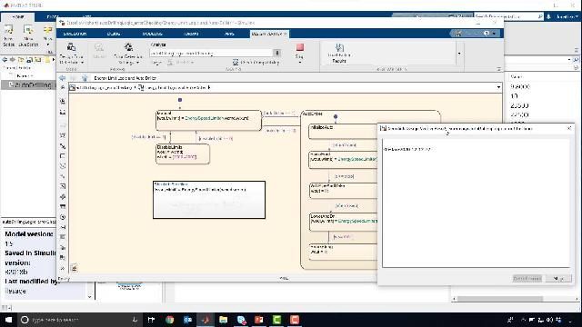
Logic verification and testing
Testing, verification and validation is performed for the drawworks control logic using formal methods. Test cases are generated at the click of a button and modeling errors are discovered.
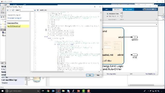
PLC code is generated for the controller and C++ code is generated for the model at the click of a button. Later, this is used for real time testing.
Real-time testing: HIL simulation
Risk-free testing and virtual drilling is performed with HIL simulations. The control algorithm is deployed on a PLC and the environment model is deployed on a real-time target machine.
Legacy PLC code is imported into Simulink for testing and validation purposes.