QPSK Transmitter and Receiver
This example shows the design and verification of a QPSK transmitter and receiver for hardware implementation. The example includes MATLAB behavioral reference code and has a parameterizable packet size.
The transmitter and receiver designs in this example show both MATLAB® reference code and a Simulink® model. The MATLAB code allows fast simulation and exploration of the design using double data types, with quantization at key locations to match the Simulink behavior. The Simulink model simulates the hardware latency and control signals, uses fixed-point data types, and supports HDL code generation. You can use the MATLAB scripts run_qpskTx to simulate the transmitter and run_qpskRx to simulate the receiver.
This example is designed for continuous data transmission and reception. Using continuous data allows the receiver to perform blind symbol timing recovery and frequency synchronization, and adapt the calculation over several packets. Systems designed for short, discrete bursts require more complex packet structures and more complex receiver algorithms to ensure the receiver synchronization algorithms can adapt quickly for each received packet.
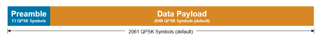
This example uses a simple packet structure with a Barker code preamble of 13 QPSK symbols and a default data payload size of 4096 bits (2048 QPSK symbols). The packet does not contain any other header information and no error correction codes or CRC are added to the data payload.
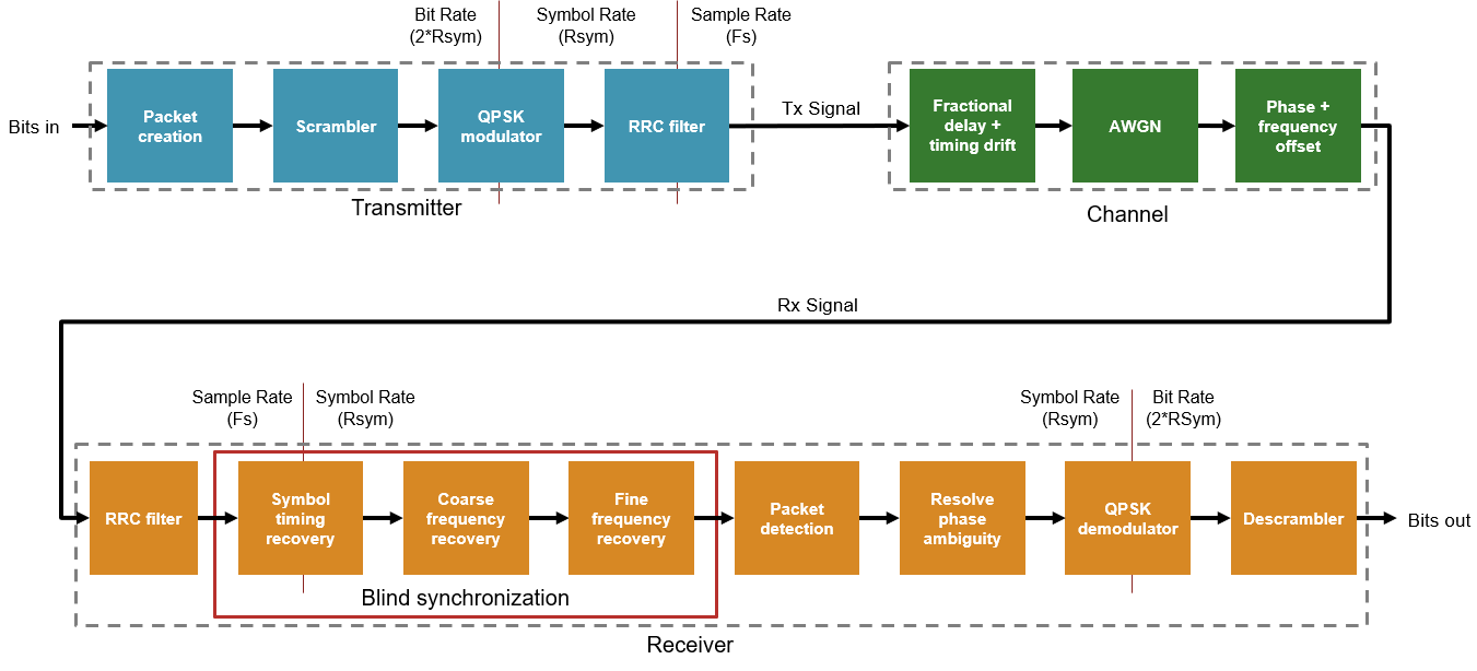
Transmitter Overview
The transmitter generates packets of scrambled data with a Barker code preamble. You can configure the size of the payload in transmitted packets. The default value is 4096 data bits per packet.

Packet Creation: Buffers incoming data into packet sized blocks and prepends the preamble bits. Implemented by
qpskTxRefin MATLAB andqpskTx/QPSK Tx/Bit Packetizerin Simulink.Scrambler - Scrambles the payload to remove long sequences of ones and zeros. Implemented by
qpskTxRefin MATLAB andqpskTx/QPSK Tx/Scramblerin Simulink.Symbol Modulator: Performs QPSK symbol modulation. Combines two bits at the input to produce each output symbol. Output rate is Rsym. Implemented by
qpskTxRefin MATLAB andqpskTx/QPSK Tx/Symbol Modulatorin Simulink.RRC Filter: Root raised cosine filter. Performs pulse shaping on the QPSK symbols and interpolates by a factor of 4. Output rate is Fs, 4 times the symbol rate (Rsym). Implemented by
qpskTxRefin MATLAB andqpskTx/QPSK Tx/FIR Interpolatorin Simulink.
Simulate Transmitter
Use the run_qpskTx.m script to simulate the MATLAB and Simulink transmitters and analyze the results. The script configures the transmitter parameters, generates bits for transmission, simulates the MATLAB transmitter (qpskTxRef.m), simulates the Simulink transmitter (qpskTx.slx), and then compares and plots the results. You can configure the number of data bits per packet and the number of packets transmitted.
>> run_qpskTx
                                 MATLAB vs Simulink
    ____________________________________________________________________________

        signalName         numSamples    RMSErr    maxAbsErr    maxPercentAbsErr
    ___________________    __________    ______    _________    ________________

    Transmitted Symbols      103050        0           0               0
    Transmitted Signal       412200        0           0               0
![]()
The figure plots the QPSK constellation and the transmitted constellation (the output from the RRC filter). The MATLAB and Simulink results for the transmitter are an exact match at the QPSK symbol modulator output and the RRC filter output.
Receiver Overview
The receiver performs a number of processing steps to recover the transmitted data bits.

RRC Filter: Non-decimating RRC filter matched to the transmit RRC filter. This stage does not decimate the signal, which allows the symbol timing recovery to compensate for any fractional delay and timing drift. Implemented by
qpskRxRefin MATLAB andqpskRx/QPSK Rx/RRC Filterin Simulink.Symbol Timing Recovery: Tracks and corrects symbol timing phase and timing drift by using a Gardner timing recovery loop. This process reduces the sample rate by a factor of 4, resulting in an output sample rate of Rsym. The signal power and SNR of the received signal impact the adaption speed and accuracy of the timing recovery algorithm. Implemented by
symbolTimingRecoveryin MATLAB andqpskRx/QPSK Rx/Time and Frequency Synchronization/Symbol Timing Recoveryin Simulink.Coarse Frequency Recovery: Performs frequency offset estimation by using a correlation-based algorithm, similar to
comm.CoarseFrequencyCompensator, with an additional signal normalization that controls word length growth in the hardware algorithm. The algorithm performs frequency estimates on blocks of samples defined byrxConfig.coarseFreqIntegAvgLen. The calculated offset affects the feedforward correction of the received symbols. The output from the frequency estimation step in MATLAB is not a bit-true match for the Simulink implementation due to the complexity of the fixed-point algorithm. A small difference in the estimated frequency offset is expected, which causes differences in later processing steps. Differences in the coarse frequency recovered symbols do not impact the receiver performance because the later processing steps can recover the received QPSK symbols and achieve the same BER. Implemented bycoarseFrequencyCorrectionin MATLAB andqpskRx/QPSK Rx/Time and Frequency Synchronization/Coarse Frequency Recoveryin Simulink.Fine Frequency Recovery: Estimates and corrects the phase offset of the signal by using a phase error detector with an NCO in a feedback loop. The estimation adapts over time to correct the remaining frequency offset. Large changes in coarse frequency estimates, which can occur in low SNR cases, negatively impact fine frequency recovery. Implemented by
fineFrequencyCorrectionin MATLAB andqpskRx/QPSK Rx/Time and Frequency Synchronization/Fine Frequency Recoveryin Simulink.Packet Detection: Detects the start of each packet by correlating the incoming signal with the known preamble sequence. Applies a dynamic threshold to the correlator output. The dynamic threshold is calculated using the magnitude squared of the received symbols over a window of
rxConfig.detectorThreshSamplessamples, scaled byrxConfig.detectorThresholdScaling. The threshold and scaling minimize false positives and ensure that valid packets are detected. The algorithm filters correlator values that exceed the dynamic threshold and selects the strongest peak within a window ofrxConfig.detectorWindowLengthsamples. After detecting the start of a packet, the algorithm ignores mid-packet correlation peaks until the expected start of the next packet. The packet detector requires a level of timing and frequency synchronization before it will detect any packets. This threshold means that the number of packets detected by the receiver might be smaller than the number of transmitted packets. Implemented bypacketDetectorin MATLAB andqpskRx/QPSK Rx/Packet Detectorin Simulink.Resolve Phase Ambiguity: The algorithm assumes that the residual frequency offset after the fine frequency recovery is negligible, and that the constellation points are correctly aligned within the quadrants. These assumptions mean the QPSK constellation is not spinning. However, QPSK constellations are rotationally symmetric and, without some knowledge of the expected orientation of the constellation, the recovered symbols can have a phase offset of 0, 90, 180, or 270 degrees compared to the transmitted symbols. The algorithm uses phase information from the packet detector to estimate and correct the phase offset. Implemented by
resolvePhaseAmbiguityin MATLAB andqpskRx/QPSK Rx/Resolve Phase Ambiguityin Simulink.QPSK Demodulator: Converts the received QPSK symbols back into bits. Produces 2 bits of data for each received QPSK symbol. Implemented by
qpskRxRefin MATLAB andqpskRx/QPSK Rx/QPSK Demodulatorin Simulink.Descrambler: Recovers the transmitted data bits by reversing the scrambling performed in the transmitter. Implemented by
qpskRxRefin MATLAB andqpskRx/QPSK Rx/Descramblerin Simulink.
Simulate Receiver
Run the run_qpskRx.m MATLAB script to simulate the receiver in MATLAB and Simulink and analyze the results. The script configures the system parameters, generates bits for transmission, simulates the MATLAB transmitter, simulates a basic channel, and then runs the MATLAB and Simulink variants of the receiver. You can then analyze and compare the receiver performance.
You can configure these parameters in the run_qpskRx script.
dataBitsPerPacket: Number of data bits in each packet. Default value is 4096 data bits (producing 2048 QPSK symbols of data per packet).numTxPackets- Number of packets to transmit. Default value is 50 packets.Rsym: Symbol rate, in Hz. Used when you setchannelConfig.carrierFrequencyOffsetand display carrier frequency offset values. Default value is 1. Set this variable to the symbol rate for your system, in Hz.channelConfig.EbN0_dB: Signal to noise ratio of the channel, specified as EbN0 in dB. The receiver operates down to an EbN0 of around 13 dB with the default parameters. Below 13 dB the coarse frequency estimates are less accurate and change more significantly between each estimate, which impairs the adaption of the fine frequency estimate and lowers the BER of the receiver. For more information, see the Receiver Algorithm Analysis section.channelConfig.carrierFrequencyOffset: Carrier frequency offset added by the channel. When you setRsymto 1, specify this parameter as a normalized frequency. When you setRsymto the symbol rate of the system, specify this parameter as the actual value of the frequency offset. The default receiver configuration can compensate for frequency offsets in the range+/- 0.065 * RSym. This value is derived from the coarse frequency estimation correlation sum length. Therun_qpskRxscript displays a warning if the applied frequency offset is close to, or exceeds, this limit. Higher noise levels and low signal power can reduce the operating range of the coarse frequency estimator.channelConfig.carrierPhaseOffset: Carrier phase offset added by the channel. Defines the starting phase of the signal prior to the application of the frequency offset. Specify this value in degrees.channelConfig.timingOffset: Fractional delay added by the channel, in the range 0 to 1, as a fraction of the channel sample rate,Fs(4 * RSym). There can be additional fractional delays from other sources present in the system.channelConfig.timingDrift: Drift in the timing offset over time in parts-per-million (PPM).rxInputScaling- Scaling of the signal at the input to the receiver, in the range 0.05 to 1. Allows for simulation of low signal power at the input to the receiver due to attenuation in the channel or the AGC, or filtering outside of the receiver.rxNumIgnoredPackets: Number of detected packets that receiver performance analysis ignores at the start of the simulation. This interval allows some time for the synchronization algorithms to adapt, so that analysis such as the BER calculation is based on the packets received after the initial synchronization algorithm has converged. The synchronization convergence time is affected by the channel noise level and the signal power at the input to the receiver, and receiver parameters, such as the loop filter gains in the symbol timing recovery and fine frequency recovery. The number of packets detected might be less than the number of packets transmitted because the packet detector requires convergence of the synchronization algorithms before it can detect the start of a packet.
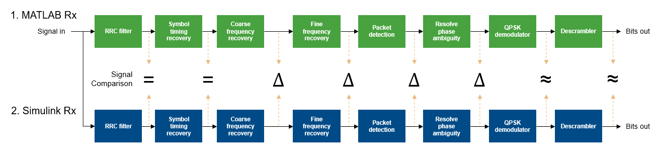
The MATLAB transmitter and basic channel model generate the test waveform for the receiver simulations. The script runs the MATLAB receiver and displays plots of the receiver behavior. The script then runs the Simulink receiver, and displays plots and tables that compare the Simulink receiver to the MATLAB receiver. The MATLAB receiver code is a bit-true match for the Simulink implementation, with the exception of the coarse frequency recovery algorithm. Some difference in the MATLAB and Simulink values is expected from the coarse frequency recovery stage onward. At high SNR values, the bits output from the MATLAB and Simulink receivers match. At low SNR values, a small number of output bits might differ between MATLAB and Simulink.
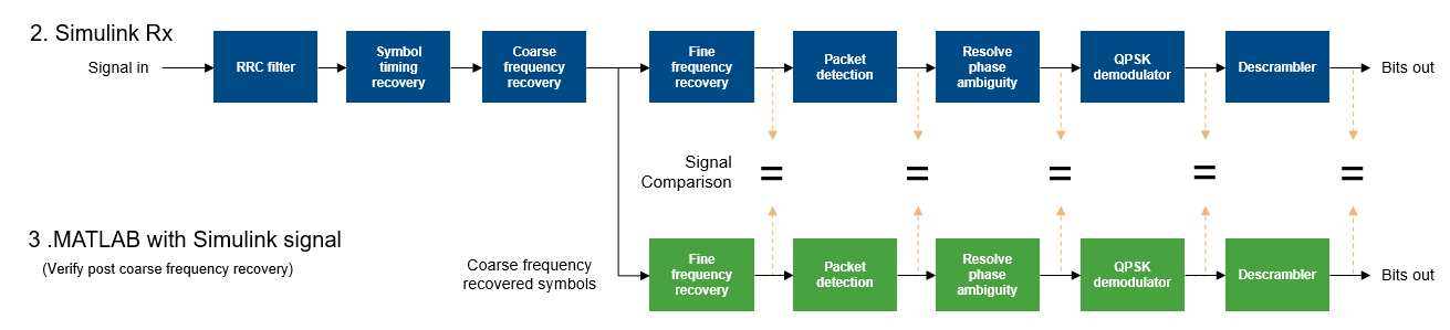
Verify the processing steps after coarse frequency compensation by rerunning the MATLAB code for these steps using the output signal from the Simulink coarse frequency recovery block. Comparison of the MATLAB and Simulink outputs shows that they are bit-true and cycle-accurate, once the differences introduced by the coarse frequency recovery stage are taken into account.
>> run_qpskRx
                   EbN0_dB: 30
    carrierFrequencyOffset: 0.0250
        carrierPhaseOffset: 0
              timingOffset: 0.5100
               timingDrift: 0
          samplesPerSymbol: 4
                sampleRate: 4

MATLAB received     : 47 packets, after initial 2 packets ignored
MATLAB bit errors   : 0
RUNNING SIMULINK MODEL
Simulink received   : 47 packets, after initial 2 packets ignored
Simulink bit errors : 0
       EbNo (dB) : 30
 Theoretical BER : 0
    Simulink BER : 0
      MATLAB BER : 0
                                 Compare Signals : MATLAB vs Simulink
    _______________________________________________________________________________________________

                signalName                numSamples      RMSErr      maxAbsErr    maxPercentAbsErr
    __________________________________    __________    __________    _________    ________________

    RRC Output                              412337               0            0               0
    Timing Recovered Symbols                103084               0            0               0
    Coarse Frequency Estimate                  100      4.7389e-06    1.006e-05        0.040261
    Coarse Frequency Corrected Symbols      103084         0.10957      0.12532          11.381
    Fine Frequency Corrected Symbols        103083      0.00049359    0.0075748          44.721
    Packet Detector Correlator Output       103083      0.00013741    0.0054164         0.95964
    Phase Corrected Symbols                 100989      0.00049868    0.0075748         0.62064


                 Compare Signals : MATLAB (with Simulink input data) vs Simulink
    __________________________________________________________________________________________

               signalName                numSamples    RMSErr    maxAbsErr    maxPercentAbsErr
    _________________________________    __________    ______    _________    ________________

    Fine Frequency Corrected Symbols       103273        0           0               0
    Packet Detector Correlator Output      103255        0           0               0
    Phase Corrected Symbols                100989        0           0               0
![]()
![]()
![]()
![]()
![]()
Receiver Performance
BER vs EbN0: With the default parameter settings, the receiver performance is limited by the frequency estimation algorithms to an EbNo around 13 dB. Below 13 dB, the coarse frequency estimates vary more between each estimation window which means that the fine frequency estimate has to compensate for step changes in the frequency offset when the coarse frequency estimate updates. You can mitigate this effect by locking the coarse frequency estimate after initial synchronization. The method of assessing and locking coarse frequency estimate depends on your application and is beyond the scope of this example.
Frequency Offset: The receiver estimates and corrects frequency offsets up to
+/- 0.065 * Rsym. For a symbol rate at the receiver input of 1.92 MHz, the maximum frequency offset is 124.8 kHz. Therun_qpskRxMATLAB script displays a warning if the channel frequency offset is close to the limit of the receiver performance.Timing Offset and Timing Drift - The receiver is designed to work with any value of constant timing offset, and a timing drift of more than 100 PPM.
Signal scaling: The receiver operates within a wide range of input signal magnitudes, and supports signal magnitudes scaled between 0.05 and 1. For optimal performance, scale the input to use the full dynamic range between +/-1. The receiver synchronization algorithms have longer convergence times when the signal power is low. When low signal power is combined with high noise levels, receiver performance is impaired.
Example File Structure
The example contains the following Simulink models and MATLAB files.
These MATLAB scripts simulate the transmitter and receiver:
run_qpskTx.m- Runs the transmitter simulation in MATLAB and Simulink. Compares the results.run_qpskRx.m- Runs the receiver simulations in MATLAB and Simulink using the MATLAB transmitter and channel to generate input stimulus. Analyzes performance and compares results.
These Simulink models implement the transmitter and receiver:
qpskTx.slx- Implements the transmitter for HDL code generation.qpskRx.slx- Implements the receiver for HDL code generation.
MATLAB supporting files:
compareSignals.m- Compares two signals.quickQuantize.m- Quantizes MATLAB variables to match Simulink fixed point data.
MATLAB supporting files for transmitter:
getQPSKTxConfig.m- Defines the QPSK transmitter configuration parameters.plotTxResults.m- Plots signals from MATLAB and Simulink transmitters at key locations.qpskTxRef.m- MATLAB reference code for the QPSK transmitter.
MATLAB supporting files for receiver:
resolvePhaseAmbiguity.m- Resolves phase ambiguity for the MATLAB receiver.symbolTimingRecovery.m- Performs symbol timing recovery for the MATLAB receiver.coarseFrequencyCorrection.m- Estimates and corrects the coarse frequency offset for the MATLAB receiver.fineFrequencyCorrection.m- Estimates and corrects the fine frequency offset for the MATLAB receiver.getQPSKRxConfig.m- Defines the QPSK receiver configuration parameters.packetDetector.m- Detects the start of each packet for the MATLAB receiver.peakPicker.m- Selects peaks in correlator output as part of the packet detector MATLAB code.plotRxCompareSignals.m- Plots comparison of MATLAB and Simulink signals at key locations in the receiver.plotRxMLSignals.m- Plots signals from the MATLAB receiver to show receiver performance.qpskRxRef.m- MATLAB reference code for the QPSK receiver.
HDL Code Generation and Implementation Results
To generate the HDL code for this example, you must have the HDL Coder™ product. Use the makehdl and makehdltb commands to generate HDL code and an HDL test bench for the qpskTx/QPSK Tx and qpskRx/QPSK Rx subsystems.
The resulting HDL code was synthesized for a Xilinx® Zynq® UltraScale+ MPSoC ZCU102 evaluation board. The table shows the post place and route resource utilization results for the transmitter and receiver. Both designs meet timing with a clock frequency of 350 MHz.
Resource utilization:
       Resource        QPSK Transmitter    QPSK Receiver
    _______________    ________________    _____________

    Slice Registers          3517              9971
    Slice LUTs               1315              6982
    RAMB18                      1                 2
    RAMB36                      0                 0
    DSP48                      18               106