Trace Boundary of Object in Image
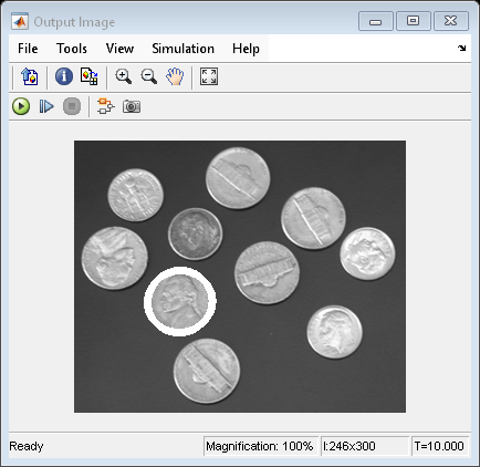
This example shows you how to trace the boundary of an object in an input image and draw that boundary on the input image.
Example Model
Open the Simulink® model.
modelname = "ex_blktraceboundary.slx";
open_system(modelname)

Note: The model uses the Fixed-step solver type. For more information on solver types, see Choose a Solver (Simulink).
This model reads the input image using the Image From File block with the File name parameter set to coins.png.
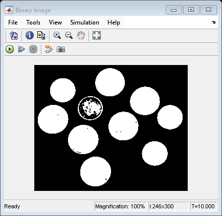
The model then converts the input image to a binary image, using the Autothreshold block.
The values at the Start Pt input port of the Trace Boundary block specify the location of the object to start tracing. This block traces boundaries of that object using these parameters:
Connectivity —
4Initial search direction —
EastTrace direction —
ClockwiseMaximum number of boundary pixels —
250
The Draw Markers block draws the traced boundaries using these parameters:
Marker shape —
PlusMarker size —
3Border color —
White
Simulate the Model
Run the model. The model displays the input image, the binary image, and the image with a boundary traced as a white circle around one coin by using Video Viewer blocks.
sim(modelname);


