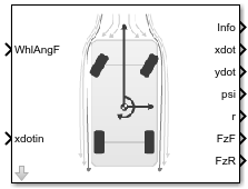
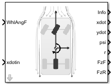
Vehicle Body 3DOF
3DOF rigid vehicle body to calculate longitudinal, lateral, and yaw motion
Libraries:
Vehicle Dynamics Blockset /
Vehicle Body
Description
The Vehicle Body 3DOF block implements a rigid two-axle vehicle body model to calculate longitudinal, lateral, and yaw motion. The block accounts for body mass and aerodynamic drag between the axles due to acceleration and steering.
This block uses the Vehicle Dynamics Blockset™ Vehicle Coordinate System. The vehicle coordinate system axes (XV, YV, ZV) are fixed in a reference frame attached to the vehicle. The coordinate system conforms to SAE J670 standard with X-forward, Y-right, Z-down orientation with origin at the center of gravity of the sprung mass. Sign convention for steer angle is positive right.
Use this block in vehicle dynamics and automated driving studies to model nonholonomic vehicle motion when vehicle pitch, roll, and vertical motion are not significant.
In the Vehicle Dynamics Blockset library, there are two types of Vehicle Body 3DOF blocks that model longitudinal, lateral, and yaw motion.
| Block | Vehicle Track Setting | Implementation |
|---|---|---|
Vehicle Body 3DOF Single Track |
|
|
Vehicle Body 3DOF Dual Track |
| Forces act at the four vehicle corners or hard points. |
Use the Axle forces parameter to specify the type of force.
| Axle Forces Setting | Implementation |
|---|---|
|
|
|
|
|
|
You can use these block parameters to create additional input ports. This table summarizes the settings.
Input Signals Pane Parameter | Input Port | Description |
|---|---|---|
Front wheel steering |
| Front wheel angle, δF |
| Rear wheel steering | WhlAngR | Rear wheel angle, δR |
| External forces | FExt | External force on vehicle center of gravity (CG), Fx, Fy, Fz, in the vehicle-fixed frame |
| External moments |
| External moment about vehicle CG, Mx, My, Mz, in vehicle-fixed frame |
| Rear hitch forces | Fh | Hitch force applied to the body at the hitch location, Fhx, Fhy, and Fhz, in the vehicle-fixed frame |
| Rear hitch moments | Mh | Hitch moment at the hitch location, Mhx, Mhy, and Mhz, about the vehicle-fixed frame |
Wind |
| Wind speed, WX, WY, WZ, in the inertial reference frame |
Air temperature | AirTemp | Ambient air temperature. Consider this option if you want to vary the temperature during run-time. |
| Friction | Mu | Ground friction coefficient |
Longitudinal position |
| Initial vehicle CG displacement along the earth-fixed X-axis |
Lateral position |
| Initial vehicle CG displacement along the earth-fixed Y-axis |
Yaw angle |
| Initial rotation of the vehicle-fixed frame about the earth-fixed Z-axis (yaw) |
Longitudinal velocity |
| Initial vehicle CG velocity along the vehicle-fixed x-axis |
Lateral velocity |
| Initial vehicle CG velocity along the vehicle-fixed y-axis |
Yaw rate |
| Initial vehicle angular velocity about the vehicle-fixed z-axis (yaw rate) |
Equations of Motion
The Vehicle Body 3DOF block implements a rigid two-axle vehicle body model to calculate longitudinal, lateral, and yaw motion. The block accounts for body mass, aerodynamic drag, and weight distribution between the axles due to acceleration and steering. To determine the vehicle motion, the block implements these equations for the single track, dual track, and drag calculations.
Single Track
| Calculation | Description |
|---|---|
|
Dynamics | The block uses these equations to calculate the rigid body planar dynamics. If you set Axle
forces to either If you set Axle
forces to |
|
External forces | External forces include both drag and external force inputs. The forces act on the vehicle CG. If you set Axle
forces to If you set Axle
forces to The block divides the normal forces by the nominal normal load to vary the effective friction parameters during weight and load transfer. The block uses these equations to maintain pitch and roll equilibrium. |
|
Tire forces | The block uses the ratio of the local and longitudinal and lateral velocities to determine the slip angles. To determine the tire forces, the block uses the slip angles. If you set Axle
forces to |
Dual Track
| Calculation | Description |
|---|---|
Dynamics | The block uses these equations to calculate the rigid body planar dynamics. If you set Axle
forces to |
External forces | External forces include both drag and external force inputs. The forces act on the vehicle CG. If you set Axle
forces to If you set Axle
forces to The block divides the normal forces by the nominal normal load to vary the effective friction parameters during weight and load transfer. The block uses these equations to maintain pitch and roll equilibrium. |
Tire forces | The block uses the ratio of the local longitudinal and lateral velocities to determine the slip angles. The block uses the steering angles to transform the tire forces to the vehicle-fixed frame. If you set Axle
forces to |
Drag
| Calculation | Description |
|---|---|
|
Coordinate transformation |
The block transforms the wind speeds from the inertial frame to the vehicle-fixed frame. |
|
Drag forces | To determine a relative airspeed, the block subtracts the wind speed from the CG vehicle velocity. Using the relative airspeed, the block determines the drag forces. |
|
Drag moments |
Using the relative airspeed, the block determines the drag moments. |
Lateral Cornering Stiffness and Relaxation Dynamics
| Description | Implementation |
|---|---|
Constant | The block uses constant stiffness values for Cyf and Cyr. |
Mapped slip angle | The block uses lookup tables that are functions of the cornering stiffness data and slip angles. |
Mapped vertical load | The block uses lookup tables that are functions of the cornering stiffness data and vertical load. |
Include relaxation length dynamics. | The slip angles include the relaxation length dynamic settings. The relaxation length approximates an effective cornering stiffness force that is a function of circumferential wheel travel. |
The equations use these variables.
| Vehicle CG displacement, velocity, and acceleration, along the vehicle-fixed x-axis | |
| Vehicle CG displacement, velocity, and acceleration, along the vehicle-fixed y-axis | |
ψ | Rotation of the vehicle-fixed frame about the earth-fixed Z-axis (yaw) |
r, |
Vehicle angular velocity, about the vehicle-fixed z-axis (yaw rate) |
| Fxf, Fxr |
Longitudinal forces applied to front and rear wheels, along the vehicle-fixed x-axis |
| Fyf, Fyr |
Lateral forces applied to front and rear wheels, along vehicle-fixed y-axis |
| Fxext, Fyext, Fzext |
External forces applied to vehicle CG, along the vehicle-fixed x-, y-, and z-axes |
| Fdx, Fdy, Fdz |
Drag forces applied to vehicle CG, along the vehicle-fixed x-, y-, and z-axes |
| Fxinput, Fyinput, Fzinput |
Input forces applied to vehicle CG, along the vehicle-fixed x-, y-, and z-axes |
| Mxext, Myext, Mzext |
External moment about vehicle CG, about the vehicle-fixed x-, y-, and z-axes |
| Mdx, Mdy, Mdz |
Drag moment about vehicle CG, about the vehicle-fixed x-, y-, and z-axes |
| Mxinput, Myinput, Mzinput |
Input moment about vehicle CG, about the vehicle-fixed x-, y-, and z-axes |
| Izz | Vehicle body moment of inertia about the vehicle-fixed z-axis |
| Fxft, Fxrt |
Longitudinal tire force applied to front and rear wheels, along the vehicle-fixed x-axis |
| Fyft, Fyft |
Lateral tire force applied to front and rear wheels, along vehicle-fixed y-axis |
| Fxfl, Fxfr |
Longitudinal force applied to front left and front right wheels, along the vehicle-fixed x-axis |
| Fyfl, Fyfr |
Lateral force applied to front left and front right wheels, along the vehicle-fixed y-axis |
| Fxrl, Fxrr |
Longitudinal force applied to rear left and rear right wheels, along the vehicle-fixed x-axis |
| Fyrl, Fyrr |
Lateral force applied to rear left and rear right wheels, along the vehicle-fixed y-axis |
| Fxflt, Fxfrt |
Longitudinal tire force applied to front left and front right wheels, along the vehicle-fixed x-axis |
| Fyflt, Fyfrt |
Lateral force tire applied to front left and front right wheels, along the vehicle-fixed y-axis |
| Fxrlt, Fxrrt |
Longitudinal tire force applied to rear left and rear right wheels, along the vehicle-fixed x-axis |
| Fyrlt, Fyrrt |
Lateral force applied to rear left and rear right wheels, along the vehicle-fixed y-axis |
| Fzf,Fzr | Normal force applied to front and rear axles, along vehicle-fixed z-axis |
| Fznom |
Nominal normal force applied to axles, along the vehicle-fixed z-axis |
| Fzfl,Fzfr |
Normal force applied to front left and right wheels, along vehicle-fixed z-axis |
| Fzrl,Fzrr |
Normal force applied to rear left and right wheels, along vehicle-fixed z-axis |
| m |
Vehicle body mass |
| a, b |
Distance of front and rear wheels, respectively, from the normal projection point of vehicle CG onto the common axle plane |
| h |
Height of vehicle CG above the axle plane |
| d | Lateral distance from the geometric centerline to the center of mass along the vehicle-fixed y-axis |
| hh | Height of the hitch above the axle plane along the vehicle-fixed z-axis |
| dh | Longitudinal distance of the hitch from the normal projection point of tractor CG onto the common axle plane |
| hl | Lateral distance from center of mass to hitch along the vehicle-fixed y-axis. |
| αf, αr |
Front and rear wheel slip angles |
| αfl, αfr |
Front left and right wheel slip angles |
| αrl, αrr |
Rear left and right wheel slip angles |
| δf, δr |
Front and rear wheel steering angles |
| δrl, δrr |
Rear left and right wheel steering angles |
| δfl, δfr |
Front left and right wheel steering angles |
| wf, wr |
Front and rear track widths |
| Cyf, Cyr |
Front and rear wheel cornering stiffness |
| Cyfdata, Cyrdata | Front and rear wheel cornering stiffness data |
| σf, σr | Front and rear wheel relaxation length |
| αfσ, αrσ | Front and rear wheel slip angles that include relaxation length |
| vwf, vwr | Magnitude of front and rear wheel hardpoint velocity |
| μf, μr |
Front and rear wheel friction coefficient |
| μfl, μfr |
Front left and right wheel friction coefficient |
| μrl, μrr |
Rear left and right wheel friction coefficient |
| Cd | Air drag coefficient acting along vehicle-fixed x-axis |
| Cs | Air drag coefficient acting along vehicle-fixed y-axis |
| Cl | Air drag coefficient acting along vehicle-fixed z-axis |
| Crm |
Air drag roll moment acting about the vehicle-fixed x-axis |
| Cpm |
Air drag pitch moment acting about the vehicle-fixed y-axis |
| Cym |
Air drag yaw moment acting about the vehicle-fixed z-axis |
| Af |
Frontal area |
| R | Atmospheric specific gas constant |
| T | Environmental air temperature |
| Pabs | Environmental absolute pressure |
| wx, wy, wz |
Wind speed, along the vehicle-fixed x-, y-, and z-axes |
| Wx, Wy, Wz |
Wind speed, along inertial X-, Y-, and Z-axes |
Examples
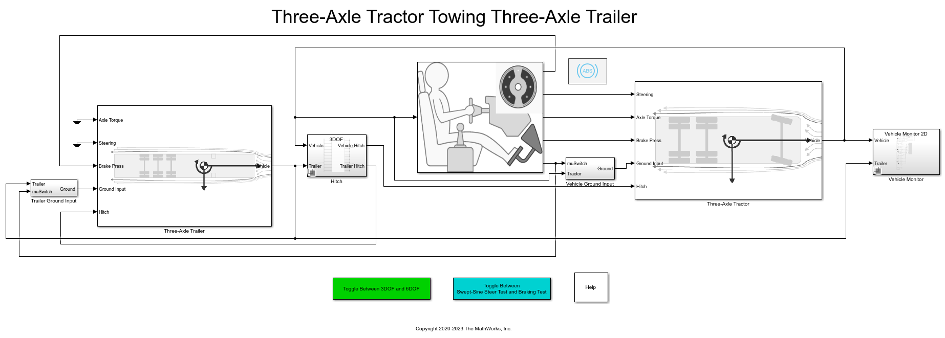
Three-Axle Tractor Towing a Three-Axle Trailer
Simulates three-axle tractor towing a three-axle trailer for commercial trucking applications. Implements hitch subsystem, sinusoidal wave steering or braking test, and axle torque applied to tractor rear wheels.
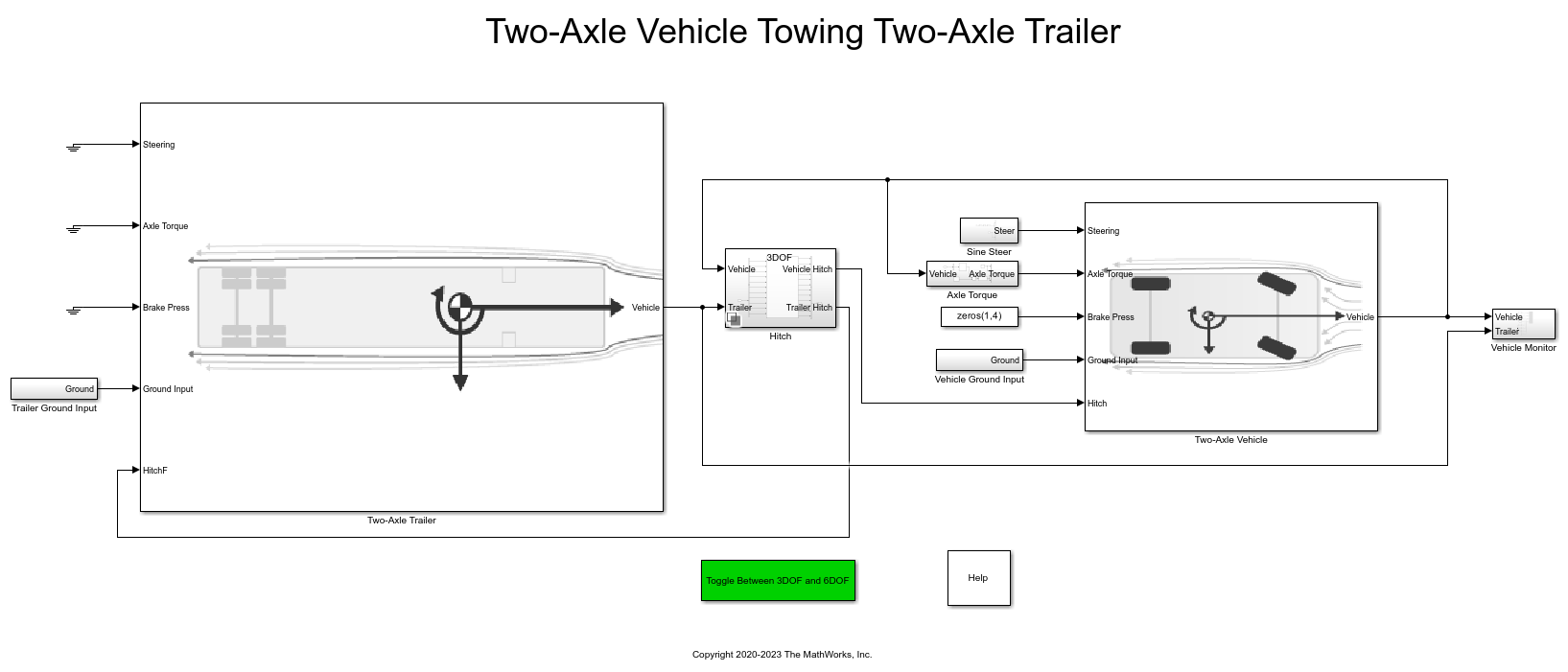
Two-Axle Tractor Towing a Two-Axle Trailer
Simulate a two-axle tractor towing a two-axle trailer for a commercial trucking application. Model implements a hitch subsystem, sinusoidal wave steering input, and an axle torque applied to the rear wheels of the tractor.
Ports
Input
Output
Parameters
Options
In the Vehicle Dynamics Blockset library, there are two types of Vehicle Body 3DOF blocks that model longitudinal, lateral, and yaw motion.
| Block | Vehicle Track Setting | Implementation |
|---|---|---|
Vehicle Body 3DOF Single Track |
|
|
Vehicle Body 3DOF Dual Track |
| Forces act at the four vehicle corners or hard points. |
Programmatic Use
To set the block
parameter value programmatically, use the set_param
function.
To get the block
parameter value programmatically, use the get_param
function.
| Parameter: | trackMode |
| Values: | Single
(bicycle) (default) | Dual |
| Data Types: | character vector |
Use the Axle forces parameter to specify the type of force.
| Axle Forces Setting | Implementation |
|---|---|
|
|
|
|
|
|
Programmatic Use
To set the block
parameter value programmatically, use the set_param
function.
To get the block
parameter value programmatically, use the get_param
function.
| Parameter: | inputMode |
| Values: | External longitudinal
velocity (default) | External longitudinal
forces | External forces |
| Data Types: | character vector |
Input Signals
Longitudinal
Horizontal distance a from the vehicle CG to the front wheel axle, in m.
Programmatic Use
To set the block parameter
value programmatically, use the set_param function.
To get the block parameter
value programmatically, use the get_param function.
| Parameter: | a |
| Values: | 1.4 (default) | scalar |
| Data Types: | double |
Horizontal distance b from the vehicle CG to the rear wheel axle, in m.
Programmatic Use
To set the block parameter
value programmatically, use the set_param function.
To get the block parameter
value programmatically, use the get_param function.
| Parameter: | b |
| Values: | 1.6 (default) | scalar |
| Data Types: | double |
Longitudinal distance from center of mass to hitch, dh, in m.
Dependencies
To enable this parameter, on the Input signals pane, select Hitch forces or Hitch moments.
Programmatic Use
To set the block parameter
value programmatically, use the set_param function.
To get the block parameter
value programmatically, use the get_param function.
| Parameter: | dh |
| Values: | 1 (default) | scalar |
| Data Types: | double |
Vertical distance from hitch to axle plane, hh, in m.
Dependencies
To enable this parameter, on the Input signals pane, select Hitch forces or Hitch moments.
Programmatic Use
To set the block parameter
value programmatically, use the set_param function.
To get the block parameter
value programmatically, use the get_param function.
| Parameter: | hh |
| Values: | 0.2 (default) | scalar |
| Data Types: | double |
Initial vehicle CG velocity along vehicle-fixed x-axis, in m/s.
Dependencies
For the Vehicle Body 3DOF Single Track or Vehicle Body 3DOF Dual Track blocks, to enable this parameter, set Axle forces to one of these options:
External longitudinal forcesExternal forces
Programmatic Use
To set the block parameter
value programmatically, use the set_param function.
To get the block parameter
value programmatically, use the get_param function.
| Parameter: | xdot_o |
| Values: | 0 (default) | scalar |
| Data Types: | double |
Lateral
Front tire cornering stiffness, Cyf, in N/rad.
Dependencies
For the Vehicle Body 3DOF Single Track or Vehicle Body 3DOF Dual Track blocks, to enable this parameter:
Set Axle forces to one of these options:
External longitudinal velocityExternal longitudinal forces
Set Mapped corner stiffness to
Constant
Programmatic Use
To set the block parameter
value programmatically, use the set_param function.
To get the block parameter
value programmatically, use the get_param function.
| Parameter: | Cy_f |
| Values: | 12e3 (default) | scalar |
| Data Types: | double |
Rear tire cornering stiffness, Cyr, in N/rad.
Dependencies
For the Vehicle Body 3DOF Single Track or Vehicle Body 3DOF Dual Track blocks, to enable this parameter:
Set Axle forces to one of these options:
External longitudinal velocityExternal longitudinal forces
Set Mapped corner stiffness to
Constant
Programmatic Use
To set the block parameter
value programmatically, use the set_param function.
To get the block parameter
value programmatically, use the get_param function.
| Parameter: | Cy_r |
| Values: | 11e3 (default) | scalar |
| Data Types: | double |
Initial vehicle CG velocity along vehicle-fixed y-axis, in m/s.
Programmatic Use
To set the block parameter
value programmatically, use the set_param function.
To get the block parameter
value programmatically, use the get_param function.
| Parameter: | ydot_o |
| Values: | 0 (default) | scalar |
| Data Types: | double |
Enables mapped cornering stiffness calculation.
Dependencies
To enable this parameter, set Axle forces to one of these options:
External longitudinal velocityExternal longitudinal forces
Programmatic Use
To set the block
parameter value programmatically, use the set_param
function.
To get the block
parameter value programmatically, use the get_param
function.
| Parameter: | CalphaMode |
| Values: | constant (default) | Mapped slip angle | Mapped vertical load |
| Data Types: | character vector |
Enables relaxation length dynamics.
Dependencies
To enable this parameter:
External longitudinal velocityExternal longitudinal forces
Programmatic Use
To set the block
parameter value programmatically, use the set_param
function.
To get the block
parameter value programmatically, use the get_param
function.
| Parameter: | sigmaMode |
| Values: | on (default) | off |
| Data Types: | character vector |
Lateral distance from geometric centerline to center of mass, d, in m, along the vehicle-fixed y. Positive values indicate that the vehicle CM is to the right of the geometric centerline. Negative values indicate that the vehicle CM is to the left of the geometric centerline.
Dependencies
To enable this parameter, set Vehicle track to
Dual.
Programmatic Use
To set the block
parameter value programmatically, use the set_param
function.
To get the block
parameter value programmatically, use the get_param
function.
| Parameter: | d |
| Values: | 0 (default) | scalar |
| Data Types: | double |
Lateral distance from geometric centerline to the hitch, hl, in m, along the vehicle-fixed y. Positive values indicate that the hitch is to the right of the geometric centerline. Negative values indicate that the hitch is to the left of the geometric centerline.
Dependencies
To enable this parameter, on the Input signals pane, select Hitch forces or Hitch moments.
Programmatic Use
To set the block
parameter value programmatically, use the set_param
function.
To get the block
parameter value programmatically, use the get_param
function.
| Parameter: | hl |
| Values: | 0 (default) | scalar |
| Data Types: | double |
Track width, w, in m.
Dependencies
To enable this parameter, set Vehicle track to
Dual.
Programmatic Use
To set the block
parameter value programmatically, use the set_param
function.
To get the block
parameter value programmatically, use the get_param
function.
| Parameter: | w |
| Values: | [1.4,1.4] (default) | 1-by-2
vector |
| Data Types: | double |
Front tire relaxation length, σf, in m.
Dependencies
To enable this parameter , set Axle forces to one of these options:
External longitudinal velocityExternal longitudinal forces
Programmatic Use
To set the block
parameter value programmatically, use the set_param
function.
To get the block
parameter value programmatically, use the get_param
function.
| Parameter: | sigma_f |
| Values: | 0.1 (default) | scalar |
| Data Types: | double |
Rear tire relaxation length, σr, in m.
Dependencies
To enable this parameter, set Axle forces to one of these options:
External longitudinal velocityExternal longitudinal forces
Programmatic Use
To set the block
parameter value programmatically, use the set_param
function.
To get the block
parameter value programmatically, use the get_param
function.
| Parameter: | sigma_r |
| Values: | 0.1 (default) | scalar |
| Data Types: | double |
Front axle slip angle breakpoints, αfbrk, in rad.
Dependencies
To enable this parameter:
Set Axle forces to one of these options:
External longitudinal velocityExternal longitudinal forces
Set Mapped corner stiffness to
Mapped slip angle
Programmatic Use
To set the block
parameter value programmatically, use the set_param
function.
To get the block
parameter value programmatically, use the get_param
function.
| Parameter: | alpha_f_brk |
| Values: | 1-by-N
vector |
| Data Types: | double |
Front axle vertical load breakpoints, Fzfbrk, in N.
Dependencies
To enable this parameter:
Set Axle forces to one of these options:
External longitudinal velocityExternal longitudinal forces
Set Mapped corner stiffness to
Mapped vertical load
Programmatic Use
To set the block
parameter value programmatically, use the set_param
function.
To get the block
parameter value programmatically, use the get_param
function.
| Parameter: | Fz_f_brk |
| Values: | 1-by-N
vector |
| Data Types: | double |
Front axle cornering stiffness data, Cyfdata, in N/rad.
Dependencies
To enable this parameter:
Set Axle forces to one of these options:
External longitudinal velocityExternal longitudinal forces
Set Mapped corner stiffness to one of these options:
Mapped slip angleMapped vertical load
Programmatic Use
To set the block
parameter value programmatically, use the set_param
function.
To get the block
parameter value programmatically, use the get_param
function.
| Parameter: | Cy_f_data |
| Values: | 1-by-N
vector |
| Data Types: | double |
Rear axle slip angle breakpoints, αrbrk, in rad.
Dependencies
To enable this parameter:
Set Axle forces to one of these options:
External longitudinal
                                        velocity
External longitudinal forces
Set Mapped corner stiffness to
Mapped slip angle
Programmatic Use
To set the block
parameter value programmatically, use the set_param
function.
To get the block
parameter value programmatically, use the get_param
function.
| Parameter: | alpha_r_brk |
| Values: | 1-by-N
vector |
| Data Types: | double |
Rear axle vertical load breakpoints, Fzrbrk, in N.
Dependencies
To enable this parameter:
Set Axle forces to one of these options:
External longitudinal
                                        velocity
External longitudinal forces
Set Mapped corner stiffness to
Mapped vertical load
Programmatic Use
To set the block
parameter value programmatically, use the set_param
function.
To get the block
parameter value programmatically, use the get_param
function.
| Parameter: | Fz_r_brk |
| Values: | 1-by-N
vector |
| Data Types: | double |
Rear axle cornering stiffness data, Cyrdata, in N/rad.
Dependencies
To enable this parameter:
Set Axle forces to one of these options:
External longitudinal
                                        velocity
External longitudinal forces
Set Mapped corner stiffness to one of these options:
Mapped slip angleMapped vertical load
Programmatic Use
To set the block
parameter value programmatically, use the set_param
function.
To get the block
parameter value programmatically, use the get_param
function.
| Parameter: | Cy_r_data |
| Values: | 1-by-N
vector |
| Data Types: | double |
Nominal normal force, in N.
Dependencies
To enable this parameter:
Set Axle forces to one of these options:
External longitudinal
                                        velocity
External longitudinal forces
Set Mapped corner stiffness to one of these options:
ConstantMapped slip angle
Programmatic Use
To set the block
parameter value programmatically, use the set_param
function.
To get the block
parameter value programmatically, use the get_param
function.
| Parameter: | Fznom |
| Values: | 5000 (default) | scalar |
| Data Types: | double |
Yaw
Rotation of the vehicle-fixed frame about earth-fixed Z-axis (yaw), in rad.
Programmatic Use
To set the block parameter
value programmatically, use the set_param function.
To get the block parameter
value programmatically, use the get_param function.
| Parameter: | psi_o |
| Values: | 0 (default) | scalar |
| Data Types: | double |
Vehicle angular velocity about the vehicle-fixed z-axis (yaw rate), in rad/s.
Programmatic Use
To set the block parameter
value programmatically, use the set_param function.
To get the block parameter
value programmatically, use the get_param function.
| Parameter: | r_o |
| Values: | 0 (default) | scalar |
| Data Types: | double |
Aerodynamic
Effective vehicle cross-sectional area, Af, to calculate the aerodynamic drag force on the vehicle, in m2.
Programmatic Use
To set the block
parameter value programmatically, use the set_param
function.
To get the block
parameter value programmatically, use the get_param
function.
| Parameter: | Af |
| Values: | 2 (default) | scalar |
| Data Types: | double |
Longitudinal drag pitch moment coefficient, Cpm. The value is dimensionless.
Programmatic Use
To set the block
parameter value programmatically, use the set_param
function.
To get the block
parameter value programmatically, use the get_param
function.
| Parameter: | Cpm |
| Values: | 0.1 (default) | scalar |
| Data Types: | double |
Side force coefficient vector coefficient, Cs. The value is dimensionless.
Programmatic Use
To set the block
parameter value programmatically, use the set_param
function.
To get the block
parameter value programmatically, use the get_param
function.
| Parameter: | Cs |
| Values: | [0 0.01:0.01:0.3] (default) |
vector |
| Data Types: | double |
Yaw moment coefficient vector, Cym. The value is dimensionless.
Programmatic Use
To set the block
parameter value programmatically, use the set_param
function.
To get the block
parameter value programmatically, use the get_param
function.
| Parameter: | Cym |
| Values: | [0 1e-6:0.01:0.3] (default) |
vector |
| Data Types: | double |
Environment
Environmental absolute temperature, T, in K.
Dependencies
To enable this parameter, clear Air temperature.
Programmatic Use
To set the block parameter
value programmatically, use the set_param function.
To get the block parameter
value programmatically, use the get_param function.
| Parameter: | Tair |
| Values: | 273 (default) | scalar |
| Data Types: | double |
Friction scale factor, μ. The value is dimensionless.
Dependencies
To enable this parameter:
Set Axle forces to one of these options:
External longitudinal
                                                  velocity
External longitudinal forces
Clear Road Friction in the Input signals pane.
Programmatic Use
To set the block parameter
value programmatically, use the set_param function.
To get the block parameter
value programmatically, use the get_param function.
| Parameter: | mu |
| Values: | 1 (default) | scalar |
| Data Types: | double |
Ground plane roll angle relative to the global inertial X axis, in deg.
Dependencies
To enable this parameter, clear Ground plane roll angle or Ground plane DCM.
Programmatic Use
To set the block parameter
value programmatically, use the set_param function.
To get the block parameter
value programmatically, use the get_param function.
| Parameter: | GndPlnRoll |
| Values: | 0 (default) | scalar |
| Data Types: | double |
Ground plane pitch angle relative to the global inertial Y axis, in deg.
Dependencies
To enable this parameter, clear Ground plane pitch angle or Ground plane DCM.
Programmatic Use
To set the block parameter
value programmatically, use the set_param function.
To get the block parameter
value programmatically, use the get_param function.
| Parameter: | GndPlnPitch |
| Values: | 0 (default) | scalar |
| Data Types: | double |
Ground plane elevation relative to the global inertial origin along the Z axis, in m.
Dependencies
To enable this parameter, clear Ground plane elevation.
Programmatic Use
To set the block parameter
value programmatically, use the set_param function.
To get the block parameter
value programmatically, use the get_param function.
| Parameter: | GndPlnElev |
| Values: | 0 (default) | scalar |
| Data Types: | double |
Simulation
Geometric longitudinal offset of the vehicle chassis from the CG along the body longitudinal axis, in m. When using the 3D visualization engine, use the offset to locate the chassis relative to the vehicle’s CG to ensure alignment with the mesh origin relative to the CG. You can also use it to report position and velocity information at any defined location.
Programmatic Use
To set the block parameter
value programmatically, use the set_param function.
To get the block parameter
value programmatically, use the get_param function.
| Parameter: | longOff |
| Values: | 0 (default) | scalar |
| Data Types: | double |
Geometric lateral offset of the vehicle chassis from the CG along the body lateral axis, in m. When using the 3D visualization engine, use the offset to locate the chassis relative to the vehicle’s CG to ensure alignment with the mesh origin relative to the CG. You can also use it to report position and velocity information at any defined location.
Programmatic Use
To set the block parameter
value programmatically, use the set_param function.
To get the block parameter
value programmatically, use the get_param function.
| Parameter: | latOff |
| Values: | 0 (default) | scalar |
| Data Types: | double |
Geometric vertical offset of the vehicle chassis from the CG along the body vertical axis, in m. When using the 3D visualization engine, use the offset to locate the chassis relative to the vehicle’s CG to ensure alignment with the mesh origin relative to the CG. You can also use it to report position and velocity information at any defined location.
Programmatic Use
To set the block parameter
value programmatically, use the set_param function.
To get the block parameter
value programmatically, use the get_param function.
| Parameter: | vertOff |
| Values: | 0.35 (default) | scalar |
| Data Types: | double |
Wrap the Euler angles to the interval [-pi, pi]. For vehicle
maneuvers that might undergo vehicle yaw rotations that are outside of the interval,
consider deselecting the parameter if you want to:
Track the total vehicle yaw rotation.
Avoid discontinuities in the vehicle state estimators.
Programmatic Use
To set the block parameter
value programmatically, use the set_param function.
To get the block parameter
value programmatically, use the get_param function.
| Parameter: | wrapAng |
| Values: | off (default) | on |
| Data Types: | character vector |
References
[1] Gillespie, Thomas. Fundamentals of Vehicle Dynamics. Warrendale, PA: Society of Automotive Engineers (SAE), 1992.