Main Content

Simulation 3D Terrain Sensor

Implement multipoint terrain sensor in 3D environment

Since R2022a

  • Simulation 3D Terrain Sensor block

Libraries:
Vehicle Dynamics Blockset / Vehicle Scenarios / Sim3D / Sim3D Vehicle / Components
Simulink 3D Animation / Simulation 3D / Sensors

Description

Note

Simulating models with the Simulation 3D Terrain Sensor block requires Simulink® 3D Animation™.

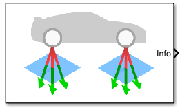
The Simulation 3D Terrain Sensor block implements a multipoint terrain sensor in Unreal Engine®. Use the block for contact modeling at high vehicle velocities over terrain changes, including speed bumps. The block implements ray tracing to detect the terrain below the tires. Use the block parameters to:

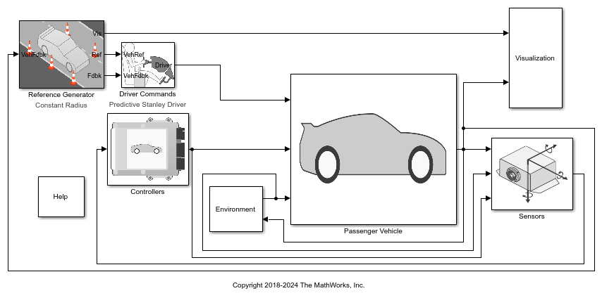
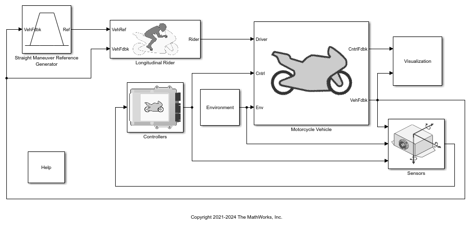
  • Sense the terrain under any simulation 3D vehicle actor in the scene, including actors created by the Simulation 3D Vehicle and Simulation 3D Motorcycle blocks.

  • Configure the ray origins, directions, and lengths to adjust the terrain sensor pattern for your scene and test scenario.

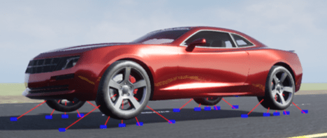
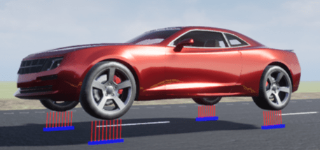
The block creates a terrain sensor pattern for each of the wheels on the vehicle actor. For specific patterns, this table provides the corresponding parameter settings.

PatternParameter Settings

Terrain sensing pattern on four-wheeled vehicle

  • Five rays per wheel

  • Rays originate at point specified by wheel spin axis

  • Rays extend downward at 15° intervals

  • Rays length is 6 m

  • Ray originszeros(5,3)

  • Ray directions[sqrt(3)/2 0 -1/2;1/2 0 -sqrt(3)/2; 0 0 -1; -1/2 0 -sqrt(3)/2; -sqrt(3)/2 0 -1/2]

  • Ray lengthsones(5,1)*6

  • Number of wheels on parent vehicle4

Terrain sensing pattern on four-wheeled vehicle

  • Five rays per wheel

  • Rays originate at point specified by .37 m wheel radius

  • Rays extend downward at 15° intervals

  • Rays length is 4 m

  • Ray originszeros(5,3)+[0 0 -.37]

  • Ray directions[sqrt(3)/2 0 -1/2;1/2 0 -sqrt(3)/2; 0 0 -1; -1/2 0 -sqrt(3)/2; -sqrt(3)/2 0 -1/2]

  • Ray lengthsones(5,1)*4

  • Number of wheels on parent vehicle4

Terrain sensing pattern on four-wheeled vehicle

  • Nine rays per wheel

  • Rays originate from points specified by .37 m wheel radius, along Y-axis of Z-up vehicle coordinate system

  • Rays extend downward, along Z-axis of Z-up vehicle coordinate system

  • Rays length is 2 m

  • Ray origins[[0.2:-0.05:-0.2];zeros(1,9);zeros(1,9)]'+[0 0 -.37]

  • Ray directionszeros(9,3)+[0 0 -1]

  • Ray lengthsones(9,1)*2

  • Number of wheels on parent vehicle4

Tip

Verify that the Simulation 3D Scene Configuration block executes before the Simulation 3D Terrain Sensor block. That way, the Unreal Engine 3D visualization environment prepares the data before the Simulation 3D Terrain Sensor block receives it. To check the block execution order, right-click the blocks and select Properties. On the General tab, confirm these Priority settings:

  • Simulation 3D Scene Configuration0

  • Simulation 3D Terrain Sensor1

For more information about execution order, see Control and Display Execution Order.
Ports

Output

expand all

Bus signal containing block values. The signals are arrays that depend on the wheel location.

SignalDescriptionUnits
WheelWPositions

Wheel W ray hit location relative to ray origin, specified as a real-valued N-by-3 array of the form [X, Y, Z] in the 3D visualization engine world coordinate system. N is the number of rays per wheel.

m

WheelWStatus

Wheel W ray hit status, specified as a N-by-1 array. N is the number of rays per wheel.

  • Hit an object – 1

  • Miss an object – 0

NA

Parameters

expand all

Mounting

Unique sensor identifier, specified as a positive integer. In a multisensor system, the sensor identifier distinguishes between sensors. When you add a new sensor block to your model, the Sensor identifier of that block is N + 1. N is the highest Sensor identifier value among existing sensor blocks in the model.

Example: 2

Name of the parent to which the sensor is mounted, specified as the name of a vehicle in your model. The vehicle names that you can select from the drop-down list correspond to the Name parameters of the simulation 3D vehicle blocks in your model.

Example: SimulinkVehicle2

Parameters

Ray origin relative to the wheel spin axis, specified as a real-valued N-by-3 array of the form [X, Y, Z]. N is the number of rays. Units are in meters.

If you mount the sensor to a vehicle by setting Parent name to the name of that vehicle, then X, Y, and Z are in the 3D visualization engine coordinate system, where:

  • The X-axis points forward from the vehicle.

  • The Y-axis points to the right of the vehicle, as viewed when looking in the forward direction of the vehicle.

  • The Z-axis points up.

Example: zeros(10,3)

Normalized ray direction relative to wheel, specified as a real-valued N-by-3 array of the form [X, Y, Z]. N is the number of rays. Units are in dimensionless.

If you mount the sensor to a vehicle by setting Parent name to the name of that vehicle, then X, Y, and Z are in the 3D visualization engine coordinate system, where:

  • The X-axis points forward from the vehicle.

  • The Y-axis points to the right of the vehicle, as viewed when looking in the forward direction of the vehicle.

  • The Z-axis points up.

Example: ones(10,3)

Ray length, specified as a real-valued N-by-1 vector N, N is the number of rays. Units are in meters.

Example: ones(10,1)*10

Number of wheels on the parent vehicle to which the sensor is mounted. The vehicle name corresponds to the Name parameters of the simulation 3D vehicle blocks in your model.

Example: 6

Enable trace line visualization.

Sample time, Ts. The graphics frame rate is the inverse of the sample time.

Version History

Introduced in R2022a

expand all