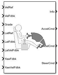
Predictive Driver
Predictive driver controller to track longitudinal speed and lateral path
Libraries:
Vehicle Dynamics Blockset /
Vehicle Scenarios /
Driver
Description
The Predictive Driver block implements a controller that generates normalized steering, acceleration, and braking commands to track longitudinal velocity and a lateral reference displacement. The normalized commands can vary between -1 to 1. The controller uses a single-track (bicycle) model for optimal single-point preview control.
Configurations
Use the External Actions parameters to create input ports for signals that you can use to simulate standard test maneuvers. The block uses this priority order for the input commands: disable (highest), hold, override.
This table summarizes the external action parameters.
| Goal | External Action Parameter | Input Ports | Data Type |
|---|---|---|---|
Override the accelerator command with an input acceleration command. | Accelerator override |
| Boolean |
| double | ||
Hold the acceleration command at the current value. | Accelerator hold | AccelHld | Boolean |
Disable the acceleration command. | Accelerator disable | AccelZero | Boolean |
Override the decelerator command with an input deceleration command. | Decelerator override |
| Boolean |
| double | ||
Hold the decelerator command at current value. | Decelerator hold | DecelHld | Boolean |
Disable the decelerator command. | Decelerator disable | DecelZero | Boolean |
Override the steering command with an input steering command. | Steering override |
| Boolean |
| double | ||
Hold the steering command at the current value. | Steering hold | SteerHld | Boolean |
Disable the steering command. | Steering disable | SteerZero | Boolean |
Use the Longitudinal control type, cntrlType parameter to specify one of these control options.
Setting | Block Implementation |
|---|---|
| Proportional-integral (PI) control with tracking windup and feedforward gains. |
| PI control with tracking windup and feedforward gains that are a function of vehicle velocity. |
| Optimal single-point preview (look ahead) control model developed by C. C. MacAdam1, 2, 3. The model represents driver steering control behavior during path-following and obstacle avoidance maneuvers. Drivers preview (look ahead) to follow a predefined path. To implement the MacAdam model, the block:
|
Use the Lateral control type, controlTypeLat parameter to specify the type of lateral control. The table specifies the block implementation.
Setting | Block Implementation | ||||||||||||
|---|---|---|---|---|---|---|---|---|---|---|---|---|---|
| Optimal single-point preview (look ahead) control model developed by C. C. MacAdam1, 2, 3. The model represents driver steering control behavior during path-following and obstacle avoidance maneuvers. Drivers preview (look ahead) to follow a predefined path. | ||||||||||||
| Controller that uses the Stanley4 method to minimize the position error and the angle error of the current pose with respect to the reference pose. On the Reference Control pane, use the:
|
Use the Shift type, ShftType parameter to specify one of these shift options.
Setting | Block Implementation |
|---|---|
| No transmission. Block outputs a constant gear of 1. Use this setting to minimize the number of parameters you need to generate acceleration and braking commands to track forward vehicle motion. This setting does not allow reverse vehicle motion. |
| Block uses a Stateflow® chart to model reverse, neutral, and drive gear shift scheduling. Use this setting to generate acceleration and braking commands to track forward and reverse vehicle motion using simple reverse, neutral, and drive gear shift scheduling. Depending on the vehicle state and vehicle velocity feedback, the block uses the initial gear and time required to shift to shift the vehicle up into drive or down into reverse or neutral. For neutral gears, the block uses braking commands to control the vehicle speed. For reverse gears, the block uses an acceleration command to generate torque and a brake command to reduce vehicle speed. |
| Block uses a Stateflow chart to model reverse, neutral, park, and N-speed gear shift scheduling. Use this setting to generate acceleration and braking commands to track forward and reverse vehicle motion using reverse, neutral, park, and N-speed gear shift scheduling. Depending on the vehicle state and vehicle velocity feedback, the block uses these parameters to determine the:
For neutral gears, the block uses braking commands to control the vehicle speed. For reverse gears, the block uses an acceleration command to generate torque and a brake command to reduce vehicle speed. |
| Block uses the input gear, vehicle state, and velocity feedback to generate acceleration and braking commands to track forward and reverse vehicle motion. For neutral gears, the block uses braking commands to control the vehicle speed. For reverse gears, the block uses an acceleration command to generate torque and a brake command to reduce vehicle speed. |
Use the Longitudinal velocity units, velUnits parameter to specify units for longitudinal velocity input ports.
Use the Angular units, angUnits parameter to specify units for yaw, steering, and pose angle input and output ports.
Use the Output gear signal parameter to create the
GearCmd output port. The GearCmd
signal contains the integer value of the commanded vehicle gear.
Gear | Integer |
|---|---|
Park |
|
Reverse |
|
Neutral |
|
Drive |
|
Gear |
|
Use the Output handwheel angle parameter to specify the units for the steering ports.
Setting | Block Implementation | Port | |
|---|---|---|---|
| Commanded road wheel steer angle, normalized from -1 through 1. The block uses the road wheel angle saturation limit parameter, Road wheel angle limit, theta, to normalize the command. |
| |
Overrides the steering command with a road wheel input steering command normalized from -1 through 1. |
| ||
| Commanded handwheel steer angle, in units specified by Angular units, angUnits. |
| |
Overrides the steering command with a handwheel input steering command, in units specified by Angular units, angUnits. |
| ||
Controller: PI Speed-Tracking
If you set the control type to PI or Scheduled
PI, the block implements proportional-integral (PI) control with tracking
windup and feedforward gains. For the Scheduled PI configuration,
the block uses feed forward gains that are a function of vehicle velocity.
To calculate the speed control output, the block uses these equations.
Setting | Equation |
|---|---|
|
|
|
|
The velocity error low-pass filter uses this transfer function.
To calculate the acceleration and braking commands, the block uses these equations.
The equations use these variables.
| vnom | Nominal vehicle speed |
| Kp | Proportional gain |
| Ki | Integral gain |
| Kaw | Anti-windup gain |
| Kff | Velocity feedforward gain |
| Kg | Grade angle feedforward gain |
| γ | Grade angle |
| τerr | Error filter time constant |
| y | Nominal control output magnitude |
| ysat | Saturated control output magnitude |
| eref | Velocity error |
| eout | Difference between saturated and nominal control outputs |
| yacc | Acceleration signal |
| ydec | Braking signal |
| v | Velocity feedback signal |
| vref | Reference velocity signal |
Controller: Predictive Speed-Tracking
If you set the Longitudinal control type, cntrlType or
Lateral control type, cntrlType to
Predictive, the block implements an optimal
single-point preview (look ahead) control model developed by C. C.
MacAdam[1], [2], [3]. The model represents driver steering control behavior during
path-following and obstacle avoidance maneuvers. Drivers preview (look ahead) to
follow a predefined path. To implement the MacAdam model, the block:
Represents the dynamics as a linear single track (bicycle) vehicle
Minimizes the previewed error signal at a single point T* seconds ahead in time
Accounts for the driver lag deriving from perceptual and neuromuscular mechanisms
For lateral and yaw motion, the block implements these linear dynamic equations.
In matrix notation:
The single-point model assumes a minimum previewed error signal at a single point T* seconds ahead in time. a* is the driver ability to predict the future vehicle response based on the current steering control input. b* is the driver ability to predict the future vehicle response based on the current vehicle state. The block uses these equations.
The equations use these variables.
| a, b | Forward and rearward tire location, respectively |
| m | Vehicle mass |
| I | Vehicle rotational inertia |
| CɑF | Front tire cornering coefficient |
| CɑR | Rear tire cornering coefficient |
| a*, b* | Driver prediction scalar and vector gain, respectively |
| x | Predicted vehicle state vector |
| v | Lateral velocity |
| r | Yaw rate |
| Ψ | Front wheel heading angle |
| y | Lateral displacement |
| F | System matrix |
| δ, δF | Steer angle and front axle steer angle, respectively |
| γ | Grade angle |
| g | Control coefficient vector |
| U | Forward (longitudinal) vehicle velocity |
| T* | Preview time window |
| ƒ(t+T*) | Previewed path input T* seconds ahead |
| u | Tractive force |
| mT | Constant observer vector; provides vehicle lateral position |
| ar | Static rolling and driveline resistance |
| br | Linear rolling and driveline resistance |
| cr | Aerodynamic rolling and driveline resistance |
| Fr | Rolling resistance |
The single-point model implemented by the block finds the steering command that minimizes a local performance index, J, over the current preview interval, (t, t+T).
To minimize J with respect to the steering command, this condition must be met.
You can express the optimal control solution in terms of a current non-optimal and corresponding nonzero preview output error T* seconds ahead1, 2, 3.
The block uses the preview distance and vehicle longitudinal velocity to determine the preview time window.
The equations use these variables.
| T* | Preview time window |
| ƒ(t+T*) | Previewed path input T* sec ahead |
| y(t+T*) | Previewed plant output T* sec ahead |
| e(t+T*) | Previewed error signal T* sec ahead |
| u(t), uo(t) | Steer angle and optimal steer angle, respectively |
| L | Preview distance |
| J | Performance index |
| U | Forward (longitudinal) vehicle velocity |
The single-point model implemented by the block introduces a driver lag. The driver lag accounts for the delay when the driver is tracking tasks. Specifically, it is the transport delay deriving from perceptual and neuromuscular mechanisms. To calculate the driver transport delay, the block implements this equation.
The equations use these variables.
| τ | Driver transport delay |
| y(t+T*) | Previewed plant output T* sec ahead |
| e(t+T*) | Previewed error signal T* sec ahead |
| u(t), uo(t) | Steer angle and optimal steer angle, respectively |
| J | Performance index |
Controller: Stanley Lateral Path-Tracking
If you set Lateral control type, controlTypeLat to
Stanley, the block implements the Stanley
method4. To compute the steering angle command, the Stanley
controller minimizes the position error and the angle error of the current pose with respect
to the reference pose. The driving direction of the vehicle determines these error
values.
To compute the steering angle command, the controller minimizes the position error and the angle error of the current pose with respect to the reference pose.
The position error is the lateral distance from the vehicle center-of-gravity (CG) to the reference point on the path.
The angle error is the angle of the vehicle with respect to reference path.
Examples
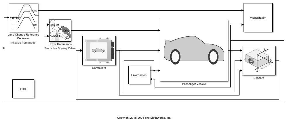
Double Lane Change Reference Application
Simulate a full vehicle dynamics model undergoing a double lane change maneuver standard ISO 3888-2. Use for vehicle dynamics ride and handling analysis and chassis controls development, including yaw stability and lateral acceleration limits.
Ports
Input
Output
Parameters
References
[1] MacAdam, C. C. "An Optimal Preview Control for Linear Systems". Journal of Dynamic Systems, Measurement, and Control. Vol. 102, Number 3, Sept. 1980.
[2] MacAdam, C. C. "Application of an Optimal Preview Control for Simulation of Closed-Loop Automobile Driving ". IEEE Transactions on Systems, Man, and Cybernetics. Vol. 11, Issue 6, June 1981.
[3] MacAdam, C. C. Development of Driver/Vehicle Steering Interaction Models for Dynamic Analysis. Final Technical Report UMTRI-88-53. Ann Arbor, Michigan: The University of Michigan Transportation Research Institute, Dec. 1988.
[4] Hoffmann, Gabriel M., Claire J. Tomlin, Michael Montemerlo, and Sebastian Thrun. "Autonomous Automobile Trajectory Tracking for Off-Road Driving: Controller Design, Experimental Validation and Racing." American Control Conference. 2007, pp. 2296–2301. doi:10.1109/ACC.2007.4282788
Extended Capabilities
Version History
Introduced in R2018a