Receive Mission and Flight Parameter Data in Simulink Using MAVLink Microservices
This example show you how to implement mission protocol and parameter protocol MAVLink microservices in Simulink to receive UAV mission and flight parameter data from QGroundControl.
Prerequisites
You must install QGroundControl to run this example.
Getting Started
Use the exampleHelperMAVLinkMissionAndParamProtocol script, attached to this example as a supporting file. The script creates an apParams variable that contains an array of 28 flight parameters.
exampleHelperMAVLinkMissionAndParamProtocol
Model Overview
Open the MissionAndParameterProtocolUsingMAVLink.slx model. This model simulates a UAV that can exchange mission and parameter data with QGroundControl using MAVLink through a UDP connection.
open_system("MissionAndParameterProtocolUsingMAVLink.slx")
The MissionAndParameterProtocolUsingMAVLink.slx model contains these sections:
Model Setup
Periodic Tx
Protocol Rx
Parameter Protocol
Mission Protocol
Mission and Parameter Protocol
Model Setup
The Model Setup section contains an Initialize Function (Simulink) block and the Global Data Stores subsystem. The MissionAndParameterProtocolUsingMAVLink.slx model uses the Initialize Function block to initialize the flight parameters that you have created by using the exampleHelperMAVLinkMissionAndParamProtocol script. The Global Data Stores subsystem contains Data Store Memory blocks that store the flight parameters.
Periodic Tx
The Periodic Tx section contain the 1 Hz subsystem that sends HEARTBEAT messages to QGroundControl, which enables QGroundControl to establish a connection with the Simulink model.
Open the 1 Hz subsystem.
blockpath = Simulink.BlockPath("MissionAndParameterProtocolUsingMAVLink/1 Hz");
open(blockpath)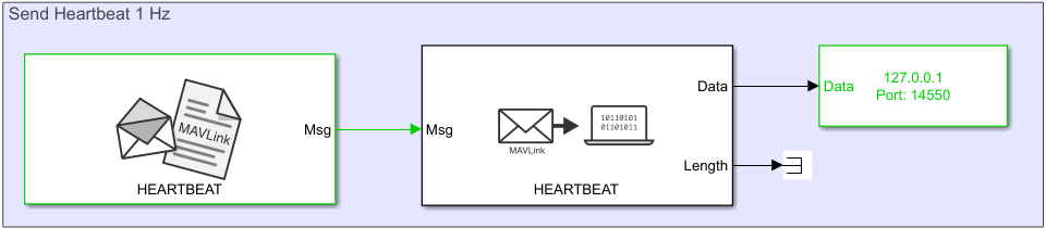
The 1Hz subsystem contains a MAVLink Blank Message block that creates the HEARTBEAT message, a MAVLink Serializer that converts the message into uint8 data stream, and a UDP Send (Instrument Control Toolbox) block that sends the HEARTBEAT message to QGroundControl through UDP.
Protocol Rx
The Protocol Rx section contains the receive_udp subsystem.
Open the receive_udp subsystem.
blockpath = Simulink.BlockPath("MissionAndParameterProtocolUsingMAVLink/receive_udp");
open(blockpath)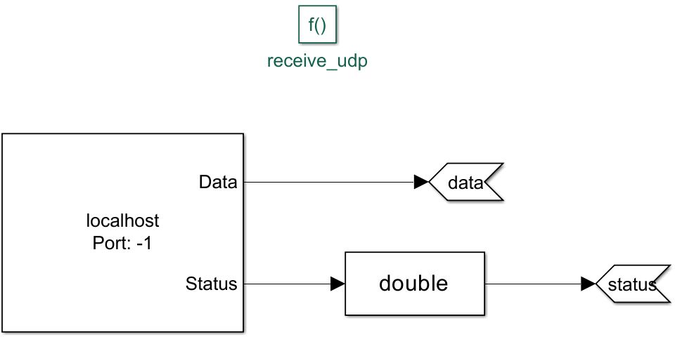
When the Mission and Parameter Protocol Stateflow® chart uses the receive_udp function, this subsystem receives MAVLink data from QGroundControl by using the UDP Receive (Instrument Control Toolbox) block. The Mission and Protocol Stateflow chart then reads and decodes this data to obtain the mission and parameter data.
Parameter Protocol
The Parameter Protocol section contains the send_param subsystem.
Open the send_param subsystem.
blockpath = Simulink.BlockPath("MissionAndParameterProtocolUsingMAVLink/send_param");
open(blockpath)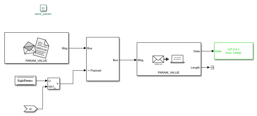
When the Mission and Protocol Stateflow chart uses the send_param function, the Bus Assignment block in this subsystem assigns the flight parameter data, stored in flightParams, to a blank PARAM_VALUE message created using the MAVLink Blank Message block. MAVLink Serializer block then converts the message into a uint8 data stream, and the UDP Send block sends the message to QGroundControl through UDP.
Mission Protocol
The Mission Protocol section contains the send_mission_request and send_mission_ack subsystems.
Open the send_mission_request subsystem.
blockpath = Simulink.BlockPath("MissionAndParameterProtocolUsingMAVLink/send_mission_request");
open(blockpath) 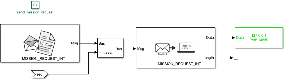
When the Mission and Protocol Stateflow chart uses the receive_udp function, the Bus Assignment block assigns the mission sequence to a blank MISSION_REQUEST_INT message created using the MAVLink Blank Message block. The MAVLink Serializer block then converts the message into a uint8 data stream, and the UDP Send block sends the message to QGroundControl through UDP.
Similarly, when the Mission and Parameter Protocol Stateflow chart uses the receive_udp function, the send_mission_ack subsystem uses the MAVLink Serializer block to convert a blank MISSION_ACK message into a uint8 data stream, and then uses the UDP Send block to send the message.
Mission and Parameter Protocol
Open the Mission and Parameter Protocol Stateflow chart.
blockpath = Simulink.BlockPath("MissionAndParameterProtocolUsingMAVLink/Mission and Parameter Protocol");
open(blockpath)
The Mission and Parameter Protocol Stateflow chart runs the mission and parameter logic at 1 Hz. The Stateflow chart consists of the ReadAndDecode and Process substates.
Read and Decode
The ReadAndDecode substate reads the MAVLink data from QGroundControl by using the receive_udp function, which outputs the data and status. The substate then uses the process_udp function to obtain the mission item, mission length, parameter read ID, and parameter write ID.
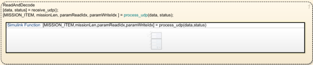
The ReadAndDecode substate implements the process_udp function as a Simulink function. Open the process_udp Simulink function.
blockpath = Simulink.BlockPath("MissionAndParameterProtocolUsingMAVLink/Mission and Parameter Protocol/ReadAndDecode.process_udp");
open(blockpath)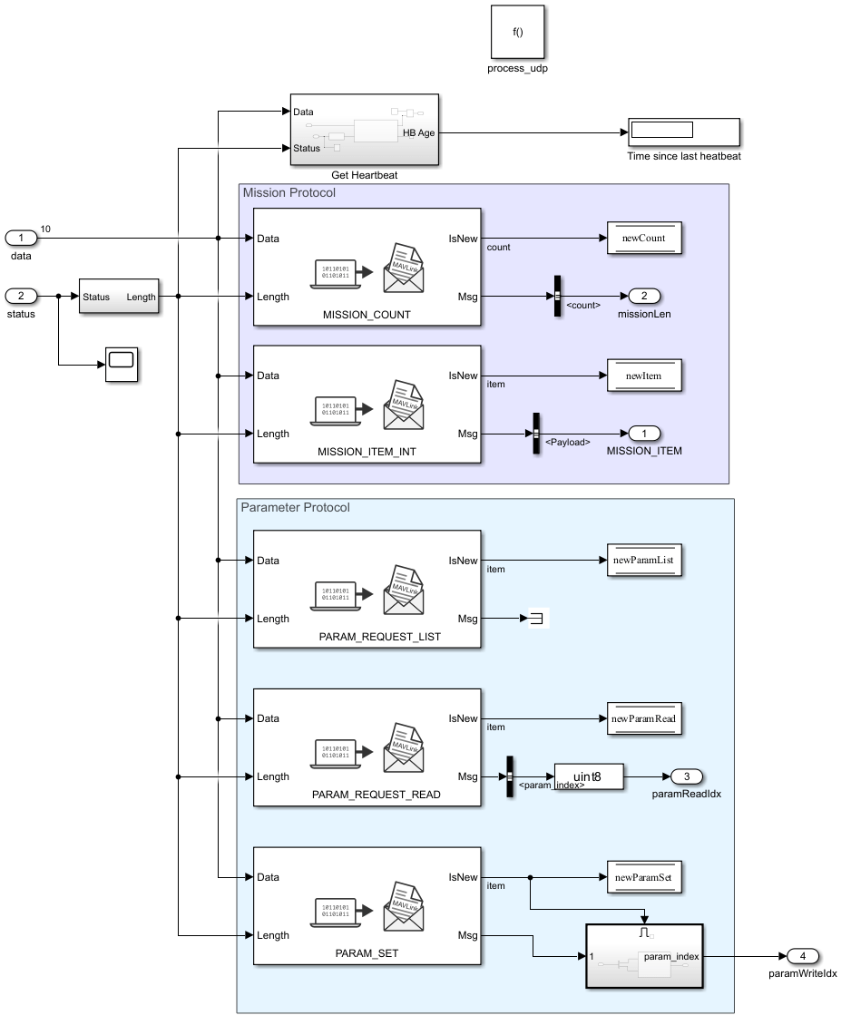
The Mission Protocol section contains MAVLink Deserializer blocks configured with these MAVLink message types:
MISSION_COUNT— This block outputs a flag to indicate if the mission count message is new, and the mission length data.MISSION_ITEM_INT— This block outputs a flag to indicate if the mission item message is new, and the mission item data.
The Parameter Protocol section contains MAVLink Deserializer blocks configured with these MAVLink message types:
PARAM_REQUEST_LIST— This block outputs a flag to indicate if the request for all parameter message is new.PARAM_REQUEST_READ— This block outputs a flag to indicate if the single parameter request message is new, and the parameter read index.
The Process substate of the Mission and Parameter Protocol Stateflow chart then uses these output flags and this data to implement the Mission Protocol MAVLink microservice.
Process
The Process substate implements the MAVLink microservices logic
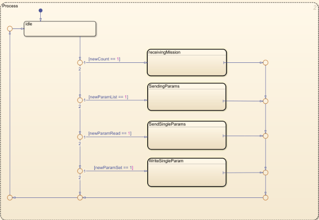
The Process substate consists of these substates:
ReceivingMission— This substate implements the Mission Protocol microservice that enables the simulated UAV model to receive missions from QGroundControl. For more details on the protocol microservice, see Upload a Mission to the Vehicle in the MAVLink documentation.SendingParams— This substate implements the Parameter Protocol microservice that enables QGroundControl to read all flight parameters of the simulated UAV model. For more details on the protocol, see Read All Parameters in the MAVLink documentation.SendSingleParams— This substate implements the Parameter Protocol microservice that enables QGroundControl to read single flight parameters of the simulated UAV model. For more details on the protocol, see Read Single Parameter in the MAVLink documentation.WriteSingleParam— This substate implements the Parameter Protocol microservice that enables QGroundControl to write flight parameters to the simulated UAV model. For more details on the protocol, see Write Parameters in the MAVLink documentation..
Receive Mission Data from QGroundControl
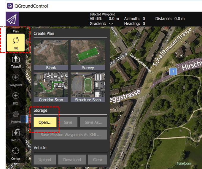
Open QGroundControl and select Fly View.
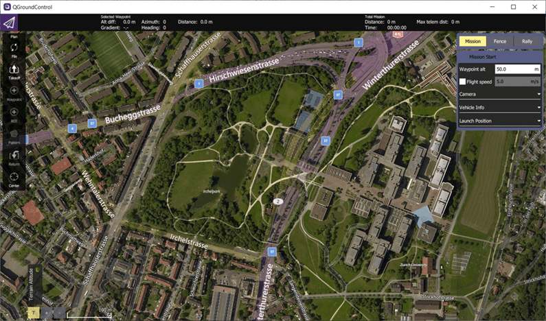
The example directory contains the MissionProtocol.plan sample flight plan. To load the sample flight plan file, from the QGroundControl toolbar, select File, then Open, and then select the MissionProtocol.plan file.
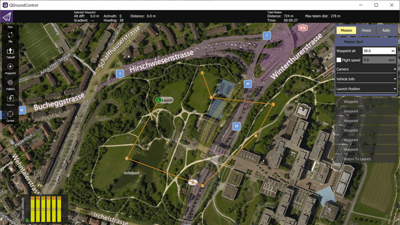
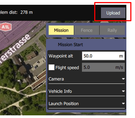
Run the MissionAndParameterProtocolUsingMAVLink.slx Simulink model. QGroundControl automatically connects to the Simulink model because it detects the HEARTBEAT message that the Simulink model sends. Once QGroundControl is connected to the Simulink model, in QGroundControl, click Upload to upload the mission from QGroundControl to the Simulink model.
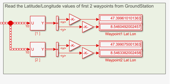
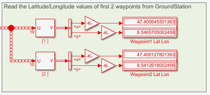
The Simulink model now displays the latitude and longitude values from the first two waypoints of the mission.
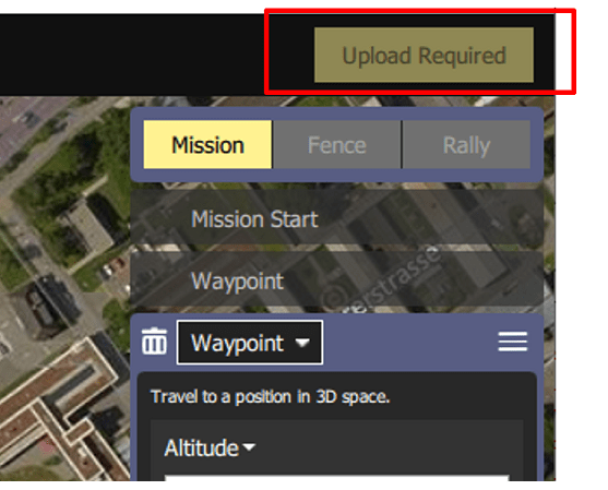
To see the effects of modifying a mission, drag the first two waypoints to new locations in QGroundControl. After you finish modifying the waypoints, you must upload the updated mission to Simulink by clicking Upload Required in QGroundControl.
The Simulink model now displays the latitude and longitude values from the first two waypoints of the modified mission.
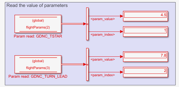
Receive Flight Parameter Data from QGroundControl
In the QGroundControl toolstrip, click Setup. In the Vehicle Setup pane, select Parameters, then Other to display all flight parameters that QGroundControl reads from the connected Simulink model.
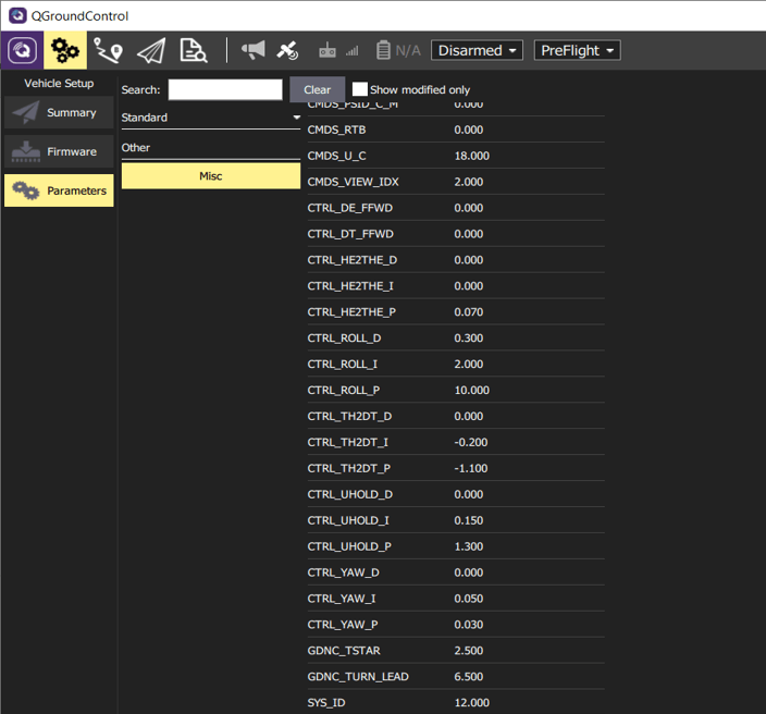
Specify values of these flight parameters:
GDNC_TSTAR —
4.500GDNC_TURN_LEAD —
7.800
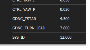
After you have updated the parameter values, QGroundControl writes these parameter to the Simulink model. The Simulink model now displays the updated flight parameter values.
See Also
MAVLink Deserializer | MAVLink Serializer