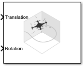
UAV Animation
Animate UAV flight path using translations and rotations
Libraries:
UAV Toolbox /
Utilities
Description
The UAV Animation block animates one or more unmanned aerial vehicle (UAV) flight paths based on an input array of translations and rotations. The output figure displays a visual mesh for either a fixed-wing or multirotor UAV at the given position and orientation in the east-north-up (ENU) coordinate system.
To automatically open the animation figure when you start the simulation, select the Always open output figure at start of simulation parameter. To manually open the figure, click Open output figure in the block mask.
Examples

Tuning Waypoint Following Controller for Fixed-Wing UAV
Design and tune a waypoint following controller for a fixed-wing UAV by using the Guidance Model and Waypoint Follower blocks.

Animate Multiple UAVs Using Dynamic Mesh
Animate multiple UAVs and dynamically adjust meshes using the UAV Animation Block.
Ports
Input
xyz-positions of the UAVs, specified as an m-by-3 matrix, where m is the total number of UAVs that you want to animate. Each row of the matrix specifies the xyz-position of a UAV in the coordinate frame that you specify in the Inertial frame z-axis direction property.
Example: [1 1 1]
Rotations of UAV body frames relative to the inertial frame, specified as an m-by-3 or m-by-4 matrix.
If you specify the Rotation format parameter as
Euler ZYX, specify this input as an m-by-3 matrix, where m is the total number of UAVs that you want to animate. Each row of the matrix represents the rotation angles about the z-, y-, and x-axes of the inertial frame for a UAV, in radians.If you specify this Rotation format parameter as
Quaternion, specify the input as an m-by-4 matrix, where m is the total number of UAVs that you want to animate. Each row of the matrix represents the quaternion vector of a UAV.
UAV mesh type, specified as an m-element vector of integers,
where m is the total number of UAVs that you want to animate. Each
element specifies the mesh type of a UAV, where 1 is a quadcopter
mesh and 2 is a fixed-wing mesh.
Dependencies
To enable this port, select the Enable dynamic UAV mesh configuration parameter.
UAV mesh configuration, specified as an m-element column vector or an m-by-4 or m-by-5 matrix. m is the total number of UAVs that you want to animate, and each row corresponds to the mesh configuration of a UAV. The size of this input depends on the parameters that you want to configure for the UAVs:
m-element column vector — Each element specifies the mesh size of a UAV, and must be a positive value. Each UAV has the default color of
[1 0 0]and alpha of1.m-by-4 matrix — Each row specifies the mesh size and color of a UAV, where the first element is the size and the other three specify the color as an RGB triplet.
m-by-5 matrix — Each row specifies the mesh size, color, and transparency of a UAV, where the first element is the size, the next three specify the color, and the last element specifies the alpha value of the UAV mesh as a value in the range
[0, 1]. A value of0is completely transparent, and a value of1is completely opaque.
Example: [10 1 0 0 0.5; 20 0 1 0 0.5] sets the first UAV mesh
size to 10 and color to red, and the second UAV mesh size to 20 and color to green.
Both UAV meshes have a transparency of 0.5.
Dependencies
To enable this port, select the Enable dynamic UAV mesh configuration parameter.
Marker configuration, specified as a n-row matrix. n is the total number of markers that you want to draw, and each row corresponds to the configuration of a marker. The size of the input depends on the parameters that you want to configure for the markers:
n-by-3 matrix — Each row specifies the xyz-position of a marker. Each row has the default size, color, type, and filled status.
n-by-4 matrix— Each row specifies the xyz- position and size of a marker, where the first 3 elements specify the position, and the last element specifies the size.
n-by-7 matrix — The first three elements specifies the xyz- position, next element specifies the size, and the other three specifies the color of a marker as a RGB triplet.
n-by-8 matrix — The first three elements specifies the xyz- position, next element specifies the size, the next three element specifies the color, and the last element specifies the type of a marker as follows:
1 — Round marker
2 — Square marker
3 — Triangle marker
n-by-9 matrix — The first three elements specifies the xyz- position, next element specifies the size, the next three element specifies the color, the next element specifies the marker type, and the last element specifies the filled status for a marker as a positive integer, with 1 being filled, and 0 being not filled.
Dependencies
To enable this port, select the Draw marker parameter.
Parameters
The number of UAV to display, specified as a positive integer.
Select this parameter to enable the UAV Type and UAV Mesh Configuration input ports, which enable you to configure different meshes for each UAV in your simulation.
Specify the mesh to display for the simulated UAVs as either
FixedWing or Multirotor. Use this parameter to
set a uniform mesh type for all UAV.
Dependencies
To enable this parameter, clear the Enable dynamic UAV mesh configuration parameter.
Use this parameter to set a uniform mesh size for all simulated UAVs. Specify the value as a positive numeric scalar.
Dependencies
To enable this parameter, clear the Enable dynamic UAV mesh configuration parameter.
Specify the color for the UAV meshes as an RGB triplet. Use this parameter to set a uniform mesh color for all the UAVs in your simulation.
Dependencies
To enable this parameter, clear the Enable dynamic UAV mesh configuration parameter.
Use this parameter to set a uniform a transparency for the meshes and trajectories of all the UAVs in your simulation.
Dependencies
To enable this parameter, clear the Enable dynamic UAV mesh configuration parameter.
Use this parameter to set the maximum number of samples that the block displays for each trajectory. Specifying a higher value enables the block to display a longer trajectory for each UAV. Specify the value as a positive integer.
Set this parameter to Down if your input translation and rotation
uses the north-east-down (NED) coordinate frame. Set this parameter to
Up if your input translation and rotation uses the east-north-up
(ENU) coordinate frame.
Note
If your input translation and rotation uses the north-east-down (NED) coordinate frame, the UAV Animation block automatically converts the rotations and translations for all UAVs and markers to output the animation in the east-north-up (ENU) coordinate system
Specify the rotation input format as one of these options:
Euler ZYX— The rotation input must be an m-by-3 matrix of Euler zyx-angles in radians, where m is the total number of UAV that you want to animate.Quaternion— The rotation input must be an m-by-4 matrix of quaternion vectors, in which each row is a quaternion. m is the total number of UAVs that you want to animate.
Select this parameter to enable the Marker input port, which enables you to draw markers in your simulation.
Specify the axis limits of the output figure plot as a 3-by-2 matrix of the form
[EastMin EastMax; NorthMin NorthMax; UpMin UpMax]. Units are in
meters.
For each axis, you can specify both an explicit minimum and maximum, or specify one
explicit limit and let the UAV Animation block automatically calculate the other limit
such that the output figure tightly fits the animated UAV or marker. To enable the block
to automatically calculate the minimum or maximum limit of an axis, specify that axis
limit as -inf or inf, respectively.
Select this parameter to automatically open the output figure when you start the simulation.
Specify the interval between outputs as a scalar, in seconds. In the simulation, the sample time follows simulation time and not actual wall-clock time.
The default value indicates that the block sample time is inherited.
For more information about the inherited sample time type, see Specify Sample Time (Simulink).
Tips
Increase the sample time to improve simulation performance. Higher sample times increase simulation speed because the block updates less frequently.
Extended Capabilities
This block can be used for animating UAV flights in systems that generate code. However, this block is not included in the generated code.
Version History
Introduced in R2018bThe output figure now displays the UAV animation in the east-north-up (ENU) coordinate system regardless of the input coordinate frame you specify to the Inertial frame z-axis direction parameter.
Previously, if you set the Inertial frame z-axis direction
parameter to Down, the block displayed UAV animations in the
west-north-up coordinate system.
The UAV Animation block now enables you to set the output figure plot axis limits by using the Plot axis limits parameter. You can specify both minimum and maximum limits for each axis, or specify one limit and let the UAV Animation block automatically calculate the other by specifying the minimum or maximum limit as
-inforinf, respectively.You can now specify the maximum number of samples that the block displays for each UAV trajectory by using the Max number of samples per trajectory parameter. Increasing the value of this parameter enables you to animate longer trajectories.
You can now configure the UAV Animation block to automatically open the output figure when you start the simulation by selecting the Always open output figure at start of simulation parameter.
The UAV Animation block now supports animating multiple UAVs. Specify the number of UAVs to animate by using the Number of UAVs parameter.
You can now draw markers by selecting the Draw marker parameter and specifying marker configurations to the Marker input port. Use markers to visualize waypoints or lookahead distance in waypoint following missions.
The UAV Animation block now supports dynamic mesh configurations which enable you to specify a different mesh configuration for each UAV in your simulation. To enable dynamic mesh configuration, select the Enable dynamic UAV mesh configuration parameter.
See Also
MATLAB Command
You clicked a link that corresponds to this MATLAB command:
Run the command by entering it in the MATLAB Command Window. Web browsers do not support MATLAB commands.
Select a Web Site
Choose a web site to get translated content where available and see local events and offers. Based on your location, we recommend that you select: .
You can also select a web site from the following list
How to Get Best Site Performance
Select the China site (in Chinese or English) for best site performance. Other MathWorks country sites are not optimized for visits from your location.
Americas
- América Latina (Español)
- Canada (English)
- United States (English)
Europe
- Belgium (English)
- Denmark (English)
- Deutschland (Deutsch)
- España (Español)
- Finland (English)
- France (Français)
- Ireland (English)
- Italia (Italiano)
- Luxembourg (English)
- Netherlands (English)
- Norway (English)
- Österreich (Deutsch)
- Portugal (English)
- Sweden (English)
- Switzerland
- United Kingdom (English)