MDF File Logging on SD Card for PX4 Autopilots
R2026bThis example shows how to use the UAV Toolbox Support Package for PX4 Autopilots to log signals from a Simulink® model to an MDF file on an SD card mounted on the PX4® autopilot. After the model runs on the target hardware, you can retrieve the logged MDF file and analyze the data in MATLAB® or Simulink®.
MDF file logging provides an efficient way to capture and store signal data generated by a model running on PX4 hardware for post-run analysis. This workflow is useful when you want to:
Record signal values during execution on target hardware.
Capture data over a fixed duration.
Analyze logged results after the run completes.
Save logged data in a file-based format suitable for historical analysis.
In this example, the model logs selected signals to an MDF file while running on the PX4 autopilot. After execution, you retrieve the logged file from the SD card and inspect the captured data.
Prerequisites
1. If you are new to Simulink, watch the Simulink Quick Start video.
2. If you have not done so already, complete the steps in Setup and Configuration.
Required Hardware
To run this example, you need:
PX4-compatible flight controller. This example uses PX4 CUAV X7+.
Micro USB cable
Micro SD card
Open Model
Open the PX4MDFFileLogging.slx model.
modelName = "PX4MDFFileLogging";
open_system(modelName)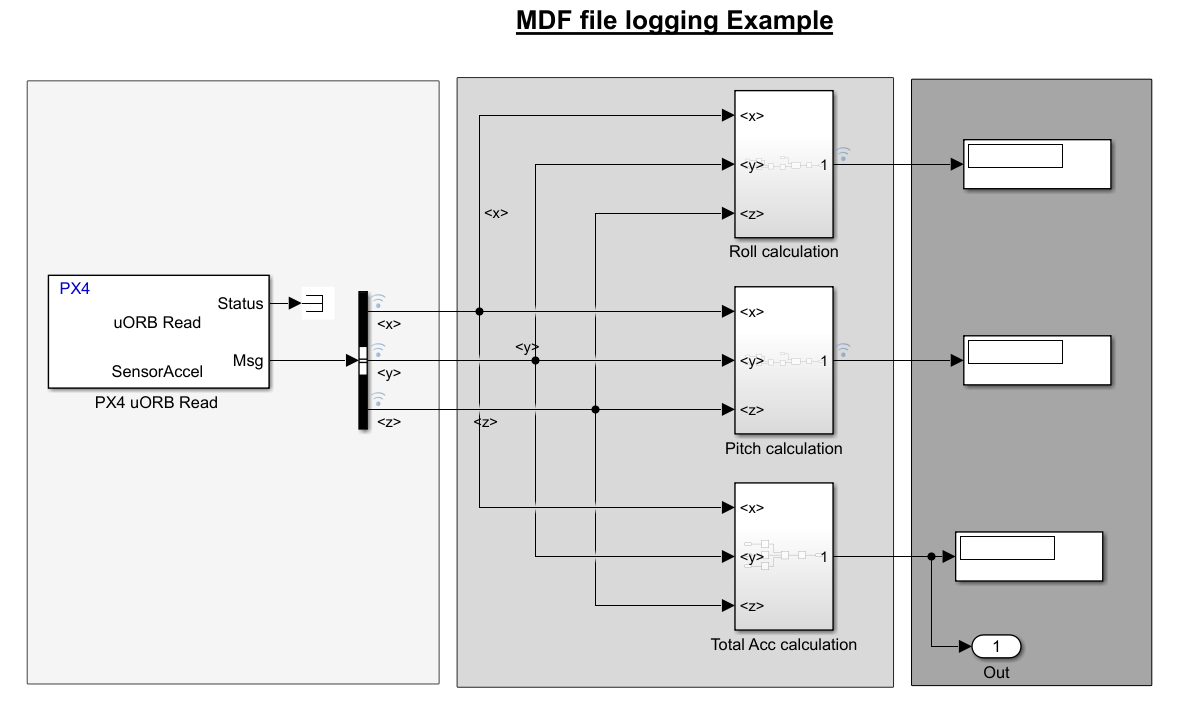
Configure MDF File Logging
The pre-configured example model is already set up for MDF file logging. Verify the following settings:
In the Simulink model, click Modeling > Model Settings to open the Configuration Parameters dialog box.
Navigate to Hardware Implementation > Target hardware resources > Build options.
In the left pane, select Code Generation > Interface.
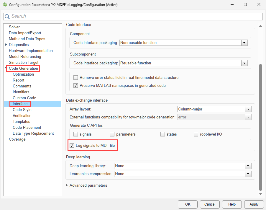
4. In the Data exchange interface section, select Log signals to MDF file.
5. Click Apply, and then click OK.
Model Overview
The model contains these main components:
PX4 uORB Read Block
The model uses a PX4 uORB Read block to subscribe to the SensorAccel topic. The block outputs accelerometer data as a bus signal. The bus is separated into the x, y, and z components and used as inputs to the calculation subsystems.
From the block parameter screenshot, the topic is set to SensorAccel, and the sample time is 0.01. That corresponds to a 100 Hz sampling rate.
Roll Calculation
The Roll calculation subsystem computes the roll angle from the accelerometer signals x, y, and z.
The roll angle is obtained using:
roll = atan2(y, sqrt(x^2 + z^2)) * (180/pi)
This computation converts the resulting angle from radians to degree
Pitch Calculation
The Pitch calculation subsystem computes pitch angle from the accelerometer components using the x, y, and z signals.
Pitch is calculated using:
pitch = atan2(x, sqrt(y^2 + z^2)) * (180/pi)
Total Acceleration Calculation
The Total Acc calculation subsystem computes the magnitude of the acceleration vector from the three accelerometer components.
Total acceleration is calculated using:
totalAcc = sqrt(x^2 + y^2 + z^2)
The subsystem uses this relationship to compute the total acceleration from the three-axis measurements.
Mark Signals for Logging
After you enable MDF logging, mark the signals that you want to store in the MDF file.
In this example, the model logs these signals:
Roll
Pitch
Total acceleration
Only signals marked for logging are written to the MDF file.
Build, Deploy, and Run the Model
Connect the PX4 hardware to the host computer.
Make sure that the SD card is inserted in the target hardware.
In the Simulink Toolstrip, on the Hardware tab, in the Mode section, click Run on board and then select Run on board (External mode). If you see Connected IO selected instead of Run on board, click on it and choose Run on board (External mode).

4. Click Build, Deploy & Start.
Wait for the build process to complete and the model to start running on the hardware.
While the model is running, the logged signals are written continuously to the MDF file on the SD card. The file is stored in the root directory of the SD card.
Analyze the Logged MDF File
After the model execution completes, retrieve the logged MDF file from the PX4 autopilot and analyze it in MATLAB.
Retrieve MDF Log File from PX4 Hardware
Use the getLogFilesFromPX4Autopilot function to retrieve the MDF log file from the SD card on the PX4 autopilot.
To retrieve the most recent MDF file corresponding to your model:
getLogFilesFromPX4Autopilot("PX4MDFFileLogging")
This function copies the most recent MDF file generated by the model from the SD card to the current folder in MATLAB.
To retrieve MDF files from all logging runs stored on the PX4 autopilot, use:
getLogFilesFromPX4Autopilot("PX4MDFFileLogging", ExtractFilesFromAllRuns=true)
Viewing the MDF File Data
You can view and analyze logged MDF data using Simulink Data Inspector.
To visualize MDF data interactively, import the MDF file into Simulink Data Inspector. Use the import workflow described in Import Data from Workspace or File into Simulation Data Inspector - MATLAB & Simulink to load MDF files and inspect logged signals.
To export logged data to a MAT-file for offline analysis or scripting, follow the workflow described in Save and Share Simulation Data Inspector Data and Views (Simulink).
For automated or custom analysis, you can access MDF files programmatically using Vehicle Network Toolbox APIs. For more information, see MDF Files - MATLAB & Simulink.
Note: The achievable logging sample rate depends on multiple factors, including the target hardware, SD card performance, model complexity, and the number of signals being logged. Higher logging rates may result in data loss depending on these conditions.
The generated MDF file uses the same base name as the model. On subsequent runs, additional MDF files are created with an incremented run count appended to the file name.
Other Things to Try
Log additional intermediate signals, such as the outputs before radians-to-degrees conversion.
Change the sample time of the
PX4 uORB Readblock and compare the effect on logged data density.Visualize the MDF file in Simulink Data Inspector and compare roll, pitch, and total acceleration over time.

