CAN Communication with Pixhawk Using Raspberry Pi
This example shows how to establish a CAN communication between Pixhawk® hardware and Raspberry Pi® hardware.
Introduction
The UAV Toolbox Support Package for PX4® Autopilots provides CAN Receive and CAN Transmit blocks that you can use to receive and send data to the CAN port on the Pixhawk Series flight controller. Similarly, Simulink® Support Package for Raspberry Pi Hardware provides CAN Receive and CAN Transmit blocks that you can use to receive and send CAN data using a MCP2515-based CAN shield. This example uses CAN blocks to establish a CAN communication between Pixhawk hardware and Raspberry Pi hardware.
Prerequisites
If you are new to Simulink, watch the Simulink Quick Start video.
For more information on how to configure the Raspberry Pi board for CAN communication, see Transmit and Receive Data Using Raspberry Pi CAN Blocks.
Required Hardware
To run this example, you will need the following hardware:
Supported PX4 Autopilot
Raspberry Pi Hardware
MCP2515-based CAN shield (for example, PiCAN 2 Duo)
Pixhawk connectors
Connecting wires
Hardware Setup
Mount PiCAN 2 Duo MCP2515 based CAN-Bus Shield on Raspberry Pi board.
Power up and Connect Raspberry Pi to the same Network. You must be able to ping the Raspberry Pi from the Host PC.
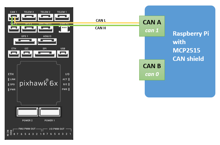
Connect Pixhawk standard 4 pin connector to the CAN 1 port of Pixhawk 6x.
Connect The Pixhawk 6x to Host PC via USB.
Use a properly terminated custom cable to link the CANH and CANL pins of the Pixhawk 6x to the CANH and CANL pins of Raspberry Pi shield.
Example Workflow
This example uses two different Simulink models.
Simulink model for CAN Communication to be deployed on PX4 Autopilot.
Simulink model for CAN Communication to be deployed on Raspberry Pi.
For better visualization of the logged data in Simulink Data Inspector, consider launching two separate sessions of same MATLAB®.
In first session of MATLAB, run the Pixhawk model in Monitor and tune Simulation (External mode).
In second session of MATLAB, run the Raspberry Pi model in Monitor and tune Simulation (External mode).
Step 1: Configure and Launch the Pixhawk CAN Communication Simulink Model
In this model, two signals (Sine wave and random noise) of data type single are sent as CAN messages. The Byte Pack block is used to convert signals of data types to a uint8 vector output. The message ID:100 is transmitted using CAN Transmit block and message ID:200 is received on CAN Receive block. The Byte Unpack block is used to convert a vector of uint8 data type to signals of data type single.
Note: To avoid conflict with PX4 UAVCAN, disable UAVCAN before working with PX4 CAN blocks. To disable, set the PX4 parameter UAVCAN_ENABLE to 0. For more information, see Finding/Updating Parameters.
Perform these steps to configure and launch the model.
1. Open MATLAB.
2. Open the example px4demo_CAN_Pixhawk model.

The example model is pre-configured for Pixhawk 6x. The model shows how to send multiple signals (for example, random noise and Sine wave) as a CAN message to the CAN bus.
3. Configure the model.
Note: Steps to configure the model is not required in the pre-configured model. Perform these step if you have changed the hardware or not using the pre-configured model.
On the Modeling tab, click Model Settings to open the Configuration Parameters dialog box.
Click Hardware Implementation and select the required PX4 hardware from the list in Hardware board parameter.
Expand Target hardware resources for that board.
Go to CAN tab.
Set the Baud rate to
500000.Note that CAN port is set to
CAN1and Test mode is set toOff.

4. Click Monitor & Tune from Run on Hardware section of Hardware tab in the Simulink Toolstrip. Wait for the Simulation to start.
Step 2: Configure and Launch the Raspberry Pi CAN Communication Simulink Model
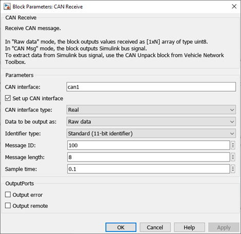
In this model, two signals (Sine wave and randon noise) of data types vector of uint8 are received as CAN messages. The Byte Unpack block is used to convert a vector of uint8 data type to signals of data type single. In this example, only the Sine wave signal is transmitted back. The Gain block is used to multiply the input by a constant value. The Byte Pack block is used to convert signal of data types to a uint8 vector output. The message ID:100 is received using CAN Receive block and message ID:200 is transmitted back to the Pixhawk model using the CAN Transmit block.
Perform these steps to configure and launch the model.
1. Open MATLAB.
2. Open the px4demo_CAN_RasPi model.

3. Configure the Model for the Raspberry Pi Hardware. Enter the IP address of the Raspberry Pi, username, and password.
4. This example model uses can1 as the CAN interface. This is the CAN A port in the CAN shield. To use CAN B port, use can0 as the CAN interface.
5. Click Monitor & Tune from Run on Hardware section of Hardware tab in the Simulink Toolstrip.
Step 3: Analyze the Signals Communicated
1. Observe the transmitted signals (random noise and Sine wave) and compare them with the signals received on the Raspberry Pi board.
2. The Sine wave is amplified with a gain of 2 and sent back to the Pixhawk model. Compare the Sine wave sent to the Raspberry Pi and the Sine wave received on Pixhawk. Change the gain value in the Raspberry Pi model and it gets reflected in the Received signal in Pixhawk.

Other Things to Try
Use NVIDIA® Jetson™ TX2 instead of Raspberry Pi. For information on getting started with CAN communication with NVIDIA Jetson, see CAN Bus Communication on NVIDIA Jetson TX2 in Simulink.
You can also select a web site from the following list:
Americas
- América Latina (Español)
- Canada (English)
- United States (English)
Europe
- Belgium (English)
- Denmark (English)
- Deutschland (Deutsch)
- España (Español)
- Finland (English)
- France (Français)
- Ireland (English)
- Italia (Italiano)
- Luxembourg (English)
- Netherlands (English)
- Norway (English)
- Österreich (Deutsch)
- Portugal (English)
- Sweden (English)
- Switzerland
- United Kingdom (English)