Activate a Simulink Block by Sending Output Events
An output event is an event that occurs in a Stateflow® chart but is visible in Simulink® blocks outside the chart. This type of event enables a chart to notify other blocks in a model about events that occur in the chart. To define an output event:
Add an event to the Stateflow chart, as described in Define Events in a Chart.
Set the Scope property for the event to
Output to Simulink. For each output event that you define, an output port appears on the Stateflow block.An output event can activate other blocks in the model through a change in a control signal (an edge trigger) or a function call to a Simulink block.
To specify an edge-triggered output event, set the Trigger property to
Either Edge.To specify a function-call output event, set the Trigger property to
Function call.
For more information, see Synchronize Model Components by Broadcasting Events.
Broadcast Output Events
To broadcast output events from one chart to another, use the operator send. The format of an
output event broadcast
is
send(event_name)
event_name is an output event.Activate a Simulink Block by Using Edge Triggers
An edge-triggered output event activates a Simulink block to execute during the current time step of simulation. With this type of output event, a change in a control signal acts as a trigger. For more information, see Using Triggered Subsystems (Simulink).
When to Use Edge-Triggered Output Events
To activate a Simulink subsystem when your model requires regular or periodic subsystem execution, use an edge-triggered output event. For example, this model uses an edge-triggered output event to activate two triggered subsystems at regular intervals.
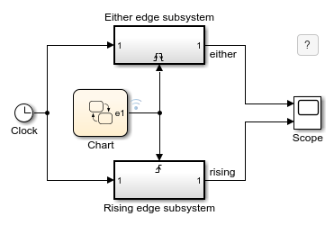
The chart contains the edge-triggered output event e1 which alternates between 0 and 1 during simulation.
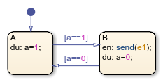
In a Stateflow chart, the Trigger property of an edge-triggered output event is always Either Edge. Simulink triggered subsystems can have a Rising, Falling, or Either edge trigger. The model shows the difference between triggering an Either edge subsystem from a Rising edge subsystem:
The output event triggers the
Eitheredge subsystem on every broadcast. The trigger occurs when the event signal switches from 0 to 1 or from 1 to 0.The output event triggers the
Risingedge subsystem on every other broadcast. The trigger occurs only when the event signal switches from 0 to 1.

Queuing Behavior of Multiple Edge-Triggered Output Events
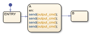
A chart dispatches only one broadcast of an edge-triggered output event for each time step. When there are multiple broadcasts in a single time step, the chart dispatches one broadcast and queues up the remaining broadcasts for dispatch in successive time steps. For example, in this model, the Caller chart uses the edge-triggered output event output_cmd to activate the Callee chart.

The Caller chart tries to broadcast the same edge-triggered output event four times in a single time step.
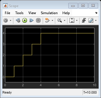
Each time the Callee chart is activated, the output data y increments by one.

When you simulate the model, at time t = 1, the Caller chart dispatches one of the four output events. The Callee chart executes once during that time step. The Caller chart queues up the other three event broadcasts for future dispatch at a time t = 2, t = 3, and t = 4. As a result, the value of y grows in increments of one at time t = 1, t = 2, t = 3, and t = 4.
Activate a Simulink Block by Using Function Calls
A function-call output event activates a Simulink block to execute during the current time step of simulation. This type of output event works only on blocks that you can trigger with a function call. For more information, see Using Function-Call Subsystems (Simulink).
When to Use Function-Call Output Events
Use a function-call output event to activate a Simulink block when your model requires access to output data from the block in the same time step as the function call. For example, this model contains two function-call output events:
In the Edge to Function chart, the output event
callactivates the Looping Scheduler chart.In the Looping Scheduler chart, the output event
A1activates a Simulink subsystem.

Interleaving Behavior of Multiple Function-Call Output Events
When there are multiple broadcasts of a function-call output event in a single time step, the chart dispatches all the broadcasts in that time step. Execution of function-call subsystems is interleaved with the execution of the chart, so that output from the function-call subsystem is available immediately in the chart. For example, in this model, the Caller chart uses the function-call output event output_cmd to activate the Callee chart.

The Caller chart tries to broadcast the same function-call output event four times in a single time step.
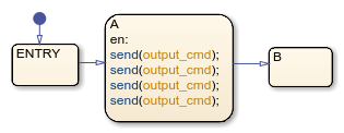
Each time the Callee chart is activated, the output data y increments by one.

When you simulate the model, the Caller chart dispatches all four output events at time t = 1. The Callee chart executes four times during that time step. Execution of the Callee chart is interleaved with execution of the Caller chart so that output from the Callee chart is immediately available. As a result, the value of | y | increases from 0 to 4 at time t = 1.

Approximate Function Call by Using Edge-Triggered Events
If you cannot use a function-call output event, such as for HDL code generation, you can approximate a function call by using:
An edge-triggered output event
An enabled subsystem
Two consecutive event broadcasts
The queuing behavior of consecutive edge-triggered output events enables you to approximate a function call with an enabled subsystem.
For example, in this model, the edge-triggered output event output_cmd activates the enabled subsystem.
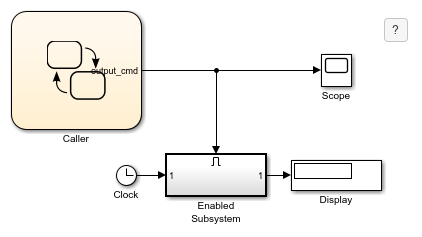
The Caller chart broadcasts the edge-triggered output event by using the send operator.

When simulation starts, the value of the trigger signal is 0. At time t = 20, the chart dispatches output_cmd, changing the value of the trigger signal to 1. The enabled subsystem becomes active and executes during that time step. Because no other event broadcasts occur, the enabled subsystem continues to execute at every time step until simulation ends at t= 40. The Display block shows a final value of 40.
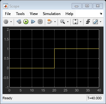
To approximate a function call, add a second event broadcast in the same action.

When simulation starts, the value of the trigger signal is 0. At time t = 20, the chart dispatches output_cmd, changing the value of the trigger signal to 1. The enabled subsystem becomes active and executes during that time step. The chart queues up the second event for dispatch at the next time step. At time t= 21, the chart dispatches the second output event, which changes the value of the trigger signal back to 0. The enabled subsystem stops executing and the Display block shows a final value of 20.

Although you can approximate a function call, there is a subtle difference in execution behavior. Execution of a function-call subsystem occurs during execution of the chart action that provides the trigger. Execution of an enabled subsystem occurs after execution of the chart action is complete.
Association of Output Events with Output Ports
When you define an output event in a chart, an output event port appears on the right side of a chart block. Output events must be scalar, but you can define multiple output events in a chart. The Port property of an output event specifies the position of the output port.
By default, Port values appear in the order in which you add output events. You can change these assignments by modifying the Port property of the events. When you change the Port property for an output event, the Port values for the remaining output events automatically renumber.