Model an Ethernet Communication Network with CSMA/CD Protocol
This example shows how to model an Ethernet communication network with CSMA/CD protocol using Simulink® messages and SimEvents®. In the example, there are three computers that communicate through an Ethernet communication network. Each computer has a software component that generates data and an Ethernet interface for communication. Each computer attempts to send the data to another computer with a unique MAC address. An Ethernet interface controls the interaction between a computer and the network by using a CSMA/CD communication protocol. The protocol is used to respond to collisions that occur when multiple computers send data simultaneously. The Ethernet component represents the network and the connection between the computers.

Software Components
In the model, each software component generates data (payload) and combines the data, its size, and its destination into a message. Then, the message is sent to the Ethernet interface for communication.
In each Software Component subsystem:
A MATLAB Function block generates data with a size between
46and1500bytes [ 1 ].
A Constant block assigns destination addresses to data.
A Bus Creator block converts the
Data,PayloadSize, andDestAddresssignals to a nonvirtual bus object calleddataPacket.
A Send block converts
dataPacketto a message.
An Outport block sends the message to the Ethernet interface for communication.

Each computer generates data with a different rate. You can change the data generation rate from the sample time of the MATLAB Function block.
To learn the basics of creating message send and receive interfaces, see Establish Message Send and Receive Interfaces Between Software Components (Simulink).
Ethernet Interface
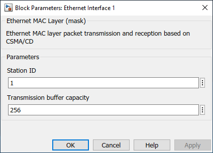
Double-click Ethernet Interface 1. Observe that you can specify the Station ID and Transmission buffer capacity.
The Ethernet Interface subsystems have three main parts:
Assemble Ethernet Frame — Converts an incoming message to an Ethernet (MAC) frame.
Transmission Buffer — Stores Ethernet frames for transmission.
Medium Access Control — Implements a CSMA/CD protocol for packet transmission [ 2 ].

Assemble Ethernet Frame
The Assemble Ethernet Frame blocks convert messages to Ethernet frames by attaching Ethernet-specific attributes to the message [ 1 ].
In the packet assembly process:
A SimEvents® Entity Replicator block labeled Copy Message copies an incoming message. The original message is forwarded to a SimEvents® Entity Generator block labeled Assemble MAC Frame. Because the Entity Generator block Generation method parameter is set to
Event-based, it immediately produces an entity when the original message arrives at the block. A copy of the message is forwarded to a Simulink Function block with theinitPacket()function. The terms message and entity are used interchangeably between Simulink® and SimEvents®.
The Simulink Function block transfers the data, its size, and its destination address to the Assemble MAC Frame block for frame assembly.
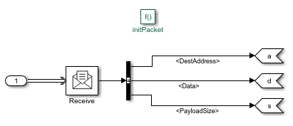
The Assemble MAC Frame block generates the Ethernet frames that carry both Ethernet-specific attributes and values transferred from the Simulink Function block.
Assemble MAC Frame block calls the initPacket() function as an action that is invoked by each frame generation event.
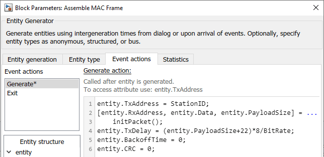
These are the attributes of the generated Ethernet frame:
entity.TxAddressisStationID.
entity.RxAddress,entity.Data, andentity.PayloadSizeare assigned the values from the Simulink Function block.
entity.TxDelayis the transmission delay. It is defined by the payload size and the bitrate. TheBitrateparameter is specified by an initialization function in the Model Properties.
entity.CRCis the cyclic redundancy check for error detection.
Transmission Buffer
The transmission buffer stores entities before transmission by using a first-in-first-out (FIFO) policy. The buffer is modeled by a Queue block.
The capacity of the queue is determined by the Transmission buffer capacity parameter.
Medium Access Control
The Medium Access Control blocks are modeled by using six SimEvents® blocks.
An Entity Gate block labeled Admit 1 Frame is configured as an enabled gate with two input ports. One input port allows frames from the Transmission Buffer block. The other input port is called the control port, which accepts messages from the CSMA/CD block. The block allows one frame to advance when it receives a message with a positive value from CSMA/CD block.
An Entity Input Switch block labeled Merge merges two paths. One input port accepts new frames admitted by the Admit 1 frame block and the other input port accepts frames for retransmission that are sent by the CSMA/CD block.
An Entity Server block labeled Wait for Channel models the back off time of a frame before its retransmission through the channel.
Another Entity Gate block labeled Send to Channel opens the gate to accept frames when the channel is idle. The channel status is communicated by the CSMA/CD chart.
An Entity Replicator block labeled Copy Transmitted Frame generates a copy of the frame. One frame is forwarded to the Ethernet network, and the other is forwarded to the CSMA/CD chart.
A Discrete-Event Chart block labeled CSMA/CD represents the state machine that models the CSMA/CD protocol.

CSMA/CD Protocol
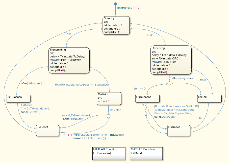
The CSMA/CD protocol [ 2 ] is modeled by a Discrete-Event Chart block that has two inputs:
TxIn— Copy of the transmitted frame.
RxIn— Received frame from the Ethernet network.
The chart has five outputs:
IsIdle— Opens the Send to Channel gate to accept frames when the value is1, and closes the gate when the value is0.
TxRe— Retransmitted frame that is forwarded to the Merge block if there is a collision detected during its transmission.
TxNext— Opens the Admit 1 Frame gate to accept new frames when the value is1.
DataOut— Received data.
Size— Size of the received data.
Transmitting and Receiving Messages
The block is initially in the Standby state and the channel is idle.
If the block is transmitting, after a delay, the block attempts to transmit the message and Isle.data is set to 0 to declare that the channel is in use.
If the transmission is successful, the block sets TxNext.data to 1 to allow a new message into the channel and resets to the Standby state.
If there is a collision, the block resends the message after delaying it for a random back off time. n is the counter for retransmissions. The block retransmits a message a maximum of 16 times. If all of the retransmission attempts are unsuccessful, then the block terminates the message and allows the entry of a new message. Then it resets to StandBy.
Similarly, the block can receive messages from other computers. If there is no error, the messages are successfully received and the block outputs the received data and its size.
Ethernet Hub
The Ethernet component represents the communication network and the cabled connections of the computers to the network.
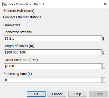
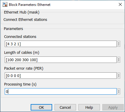
Double-click the Ethernet block to see its parameters.
Connected stations — These values are assigned to
Stations, which is a vector with the station IDs as elements.
Length of cables (m) — These values are assigned to
CableLengthand represent the length of the cables, in meters, for each computer connected to the hub.
Packet error rate (PER) — These values are assigned to
PERand represent the rate of error in message transmission for each computer.
Processing time (s) — These values are assigned to
ProcessingTimeand it represents the channel transmission delay.
Three SimEvents® blocks are used to model the Ethernet network. The three computer connections are merged by using an Entity Input Switch block. An Entity Server block is used to model the channel transmission delay based on the cable length. An Entity Replicator block copies the transmitted message and forwards it to the three computers.

Simulate the Model and Review the Results
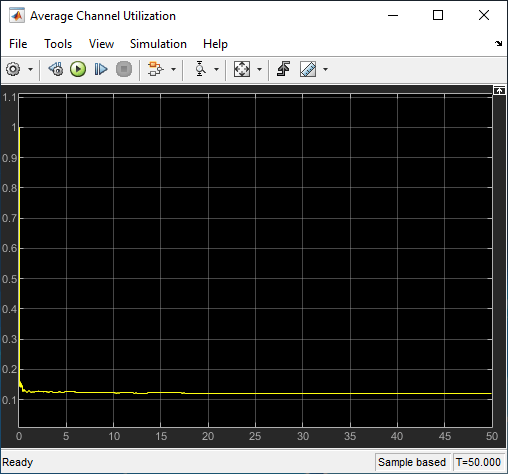
Simulate the model and open the Scope block that displays the average channel utilization. The channel utilization converges to approximately 0.12.
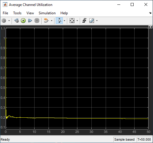
Open Software Component 1 as a top model and change the data generation rate by setting the Sample time of the Generate Data 1 block to 0.01. Run the simulation again and observe that the channel utilization increases to 0.2.
Connect New Computers to the Network
You can connect more computers to the network.
To add a new computer to the network:
Copy an existing computer and assign a new ID by double-clicking the Ethernet Interface block. In this example, new computer has ID
4.
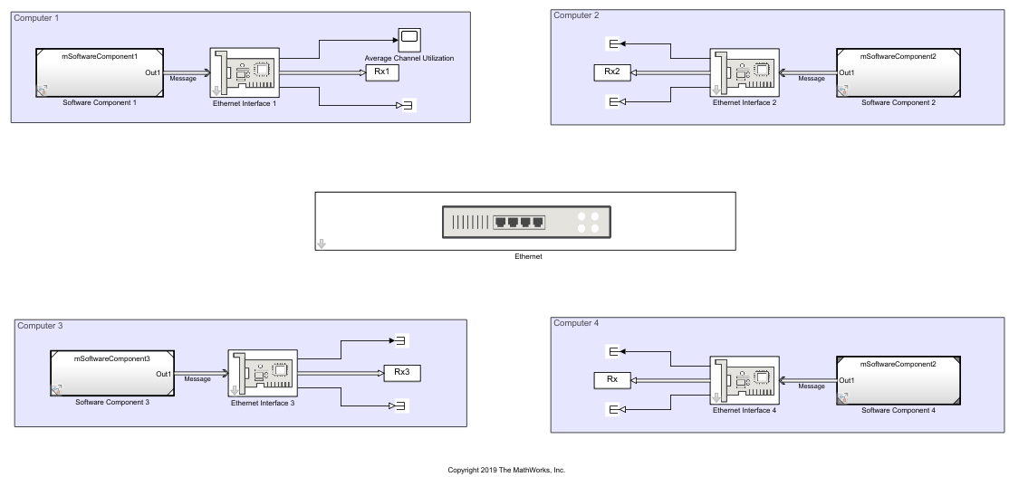
Double-click the Ethernet block and add a station ID, cable length, and packet error rate for the new computer.
References
Ethernet frame - Wikipedia (https://en.wikipedia.org/wiki/Ethernet_frame)
Carrier-sense multiple access with collision detection - Wikipedia (https://en.wikipedia.org/wiki/Carrier-sense_multiple_access_with_collision_detection)
See Also
Send (Simulink) | Receive (Simulink) | Queue (Simulink) | Entity Input Switch (SimEvents) | Entity Replicator (SimEvents) | Discrete-Event Chart (SimEvents) | Entity Generator (SimEvents) | Entity Gate (SimEvents)