Unipolar Stepper Motor with Control
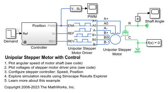
This example shows how to model a controlled permanent magnet stepper motor by using the Unipolar Stepper Motor and Unipolar Stepper Motor Driver blocks. The model has two controller options: one to control position and one to control speed. To change the controller type, right-click the Controller subsystem, select Variant > Label Mode Active Choice, and then select Position or Speed. The stepper has a full step size of 1.8 degrees. In position control mode, the input to the Ref port is the desired number of steps. In speed control mode, the input to the Ref port is the desired number of steps per second.
This model is suitable for studying the dynamics of the stepper motor at system-level and determining whether the step angle slips when driving a given load. You can use the model to tune the stepper controller to improve stepping performance. You can also implement the controller, partly or fully, on an off-the-shelf stepper controller module. Implementing the algorithm on a microprocessor, such as a peripheral interface controller (PIC), gives greater flexibility, and you can also use the microprocessor to control other parts of the system. You can implement parts of the Unipolar Stepper Motor Driver block on the microprocessor, leaving only the power amplifier stage in analog electronics.
Open Model

View Simulation Results for Position Control Test
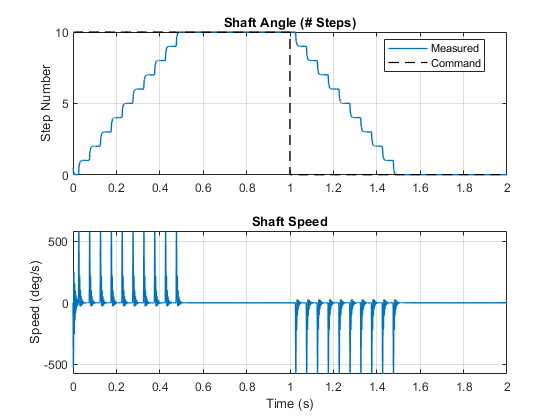
This plot compares the motor shaft angle to the demand signal when you use the position controller. The position control algorithm accepts the position command as a number of steps and converts the command into a pulse train that controls the stepper motor driver. The spikes on the angular velocity plot occur when the shaft settles into its commanded position.

View Simulation Results for Speed Control Test
This plot compares the motor shaft angle to the demand signal when you use the speed controller. The speed control algorithm accepts the speed command as a number of steps per second and converts the command into a pulse train that controls the stepper motor driver. The spikes on the angular velocity plot occur when the shaft settles into the current step.

This plot shows how the states of the pins on the stepper driver affect the motion of the stepper motor. The driver initiates a step each time the enable (ENA) signal rises above the value of the Enable threshold voltage parameter of the Unipolar Stepper Motor Driver block. The driver sets the common connections A0 and B0 to always be high, and grounds the A+, A-, B+ and B- as required.

See Also
Unipolar Stepper Motor | Unipolar Stepper Motor Driver