Impact of GIC on Autotransformer Saturation
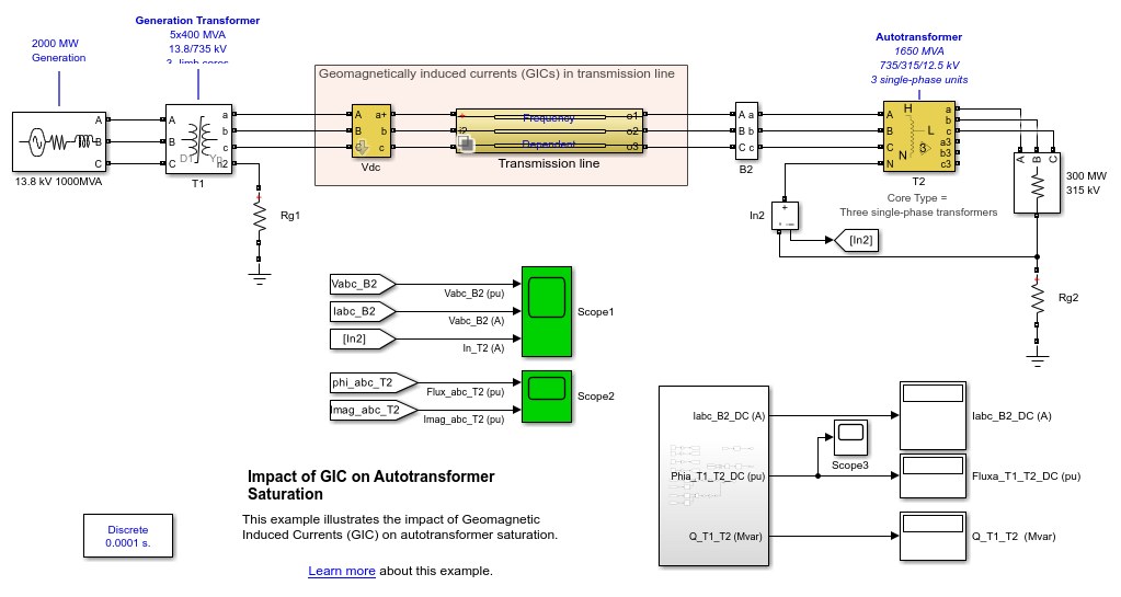
This example illustrates the impact of Geomagnetic Induced Currents (GIC) on autotransformer saturation.

Description
According to [1], GeoMagnetic Disturbances (GMDs) occur when earth is subjected to changes in the energized particle streams emitted by the Sun. Near the Earth's surface, these changes induce currents, known as geomagnetically induced currents (GICs), in long electrical conductor systems such as electric power transmission and distribution lines, communication lines, rail lines, and pipelines. Under strong GIC, transformers become a source of significant current harmonics due to saturation of their magnetic cores.
The example shows a 735-kV transmission network consisting of a 13-8 kV, 2000 MW generating station (10000-MVA short-circuit level), a 200-km, 735-kV transmission line, a 735/315/12.5 kV, a 1650-MVA autotransformer T2 and a 300-MW load. Autotransformer T2 is built with three single-phase cores, whereas generation transformer T1 uses a 3-limb core. A geomagnetic disturbance is producing a uniform 8 V/km electric field aligned with the transmission line. The resulting DC voltages induced on the transmission line are simulated by three DC voltage sources in series with the line (Vdc = 8*200= 1600 V).
As GIC currents are strongly dependent on line resistances, it is important to use a line model yielding an accurate resistance for both AC and DC phenomena. The line is modeled with the Distributed Parameters Line Frequency Dependant block and associated MAT file.
Simulation
Run simulation for 10 sec in order to reach steady state. While simulating, observe voltage and current waveforms on Scope1 as well as T2 fluxes and magnetization currents on Scope2. DC components of line currents (GICs), DC component of T1 and T2 fluxes, as well as reactive powers absorbed by T1 and T2 are shown on the Display blocks.
Note the large DC component of T2 fluxes (+ 0.67 pu). Transformer T2 is therefore strongly saturated (See fluxes and Imag waveforms on Scope2). Large non sinusoidal magnetization currents of T2 result in strong harmonic voltage and current distortions (Scope1). Also, the 60-Hz component of magnetizing currents results in large reactive power absorption (Q_T2= 424 Mvar). On the opposite, transformer T1 which uses a 3-limb core has a low DC flux offset. The DC flux of T1 is still decreasing very slowly at t=10 s (see Scope3) and in order to reach steady state you would need to simulate during several hundreds of seconds.
Impact of Autotransformer T2 Core Type
Although it is unlikely to build such a large power autotransformer (1650 MVA) with a single three-phase core, you will now observe impact of using a 3-limb core for T2.
In T2 block menu, change the Core type parameter from Three single-phase units to Three-limb core (core type) and run a new simulation. Observe that the transformer does not saturate anymore. DC fluxes of both T1 and T2 are decreasing very slowly and a simulation of several hundreds of seconds would be required to reach steady state.
In case of a 3-limb core, the three equal DC current components of magnetization currents produce a zero-sequence flux component which must circulate outside of the iron core, through the air and the tank. The high reluctance of this flux return path produces a low DC flux component, thus preventing transformer saturation.
Impact of Line Model
The three line currents resulting from DC voltages induced along the line produce three equal DC currents (zero-sequence) which will return through the ground below the line. In DC, this ground return resistance is null, except for the grounding resistances at the two substations.
If you use a Distributed Parameter Line with constant RLC parameters, the ground resistance is determined by the positive- and zero-sequence line resistances (r1 and r0 parameters in ohms/km computed at 50 or 60 Hz). For a line of length L, this ground resistance in DC will be the same as the resistance specified at 50 or 60 Hz and will be given by Rline_ground = (r0-r1)/3*L ohms, whereas it should be zero.
To observe the impact of using a Distributed Parameter line (DPL) instead of the Frequency-Dependent (FD) line, set the Variant choice of the Transmission line block to Choice_2 (DPL 735-kV 200 km). Set the T2 Core type back to Three single-phase units. Run simulation and observe that GICs have dramatically decreased from 295 A to ~25 A. Use of the DPL line model gives wrong GIC because the DPL ground resistance at 0 Hz is the same as the ground resistance at 60 Hz whereas it should be zero.
References
Geomagnetic Disturbance Monitoring, Approach and Implementation, United States Department of Energy, January 2019
Impact of GIC on Transformers and the Transmission Network, Dietrich Bonmann, ABB AG Bad Honnef, March 2016
