Input Admittance Response of RLC Ladder Network with Mutual Coupling Between Multiple Coils
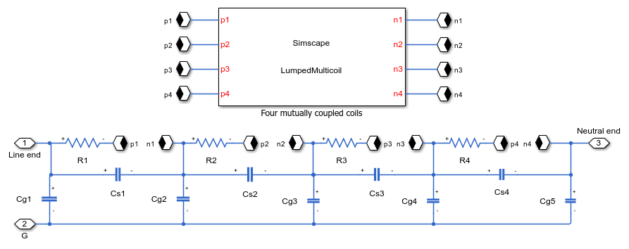
This example shows how to model a four-section ladder network that comprises RLC components with mutual coupling between multiple coils. You can use this ladder network representation to model the disc winding of a transformer. The number of sections of a ladder network depends on the number of discs in the winding. Each section can model two or three discs in the winding.
The winding resistance and self-inductance are represented as Rs and Ls for each section. The series capacitance, Cs, and the ground capacitance, Cg, model the inter-disc capacitance and the capacitance between the winding and ground, respectively.
In this example, each section is mutually coupled with three other sections. You can model the inductance of the four sections and incorporate the mutual inductance by using either a Lumped Inductance block or Distributed Inductance blocks.
To calculate the mutual inductance, each inductor must connect to the input port of the other three inductors. Because the Lumped Inductance block models the entire inductance of all sections, use this block to minimize the clustering of the branches.
The Distributed Inductance blocks model the four inductors. These blocks receive the derivative of the four branch currents as physical signals, and output the derivative of the branch current of the section.
Open the Model

Model the Ladder Network with a Lumped Inductance Block
The Lumped Inductance block models the self inductance, Ls, of the four sections lumped with the mutual inductances between each section. The Lumped Inductance block comprises the phase and neutral connections, which are labeled p and n in the diagram.

Model the Ladder Network with Multiple Distributed Inductance Blocks
Each section comprises an Inductor block that inputs the derivative of branch currents from the three other sections as physical signals and outputs the derivative of its branch current as a physical signal.

Set Up the Input Admittance Measurement
This example estimates the input admittance response of the ladder network through a voltage sensor and a controlled current source. The Input Admittance Measurement Setup subsystem calculates the system transfer function. The admittance response is then computed as the reciprocal of the estimated transfer function.

Simulation Results
The plot below shows the input admittance magnitude response for a four section ladder network.

Results from Real-Time Simulation
This example has been tested on a Speedgoat Performance real-time target machine with an Intel® 3.5 GHz i7 multi-core CPU. This model can run in real time with a step size of 10 microseconds.