Main Content

PMSM (Six-Phase)

Six-phase permanent magnet synchronous motor with sinusoidal flux distribution

Since R2020b

Libraries:
Simscape / Electrical / Electromechanical / Permanent Magnet

Description

The PMSM (Six-Phase) block models a permanent magnet synchronous machine (PMSM) with a six-phase star-wound stator. Use this block to model these types of motor if the motor has six stator windings: an interior permanent magnet synchronous machine (IPMSM), surface permanent magnet synchronous machine (SPMSM), axial flux (pancake) motor, or PMSM servomotor.

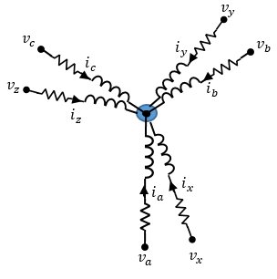
A six-phase PMSM has two groups of three-phase stator windings: the ABC group and the XYZ group. These two groups have a 30 degree phase shift.

The figure shows the equivalent electrical circuit for the stator windings.
Equations

The voltages across the stator windings are

[vavbvcvxvyvz]=[Rs000000Rs000000Rs000000Rs000000Rs000000Rs][iaibicixiyiz]+[dψadtdψbdtdψcdtdψxdtdψydtdψzdt],

where:

  • va, vb, and vc are the individual phase voltages from port ~ABC to neutral port n1.

  • vx, vy, and vz are the individual phase voltages from port ~XYZ to neutral port n2.

  • Rs is the equivalent resistance of each stator winding.

  • ia, ib, and ic are the currents flowing from port ~ABC to port n1.

  • ix, iy, and iz are the currents flowing from port ~XYZ to port n2.

  • dψadt,dψbdt,dψcdt dψxdt, dψydt, and dψzdt are the rates of change for the magnetic flux in each stator winding.

The permanent magnet and the six windings contribute to the total flux linking each winding. The total flux is

[ψaψbψcψxψyψz]=[LaaLabLacLaxLayLazLbaLbbLbcLbxLbyLbzLcaLcbLccLcxLcyLczLxaLxbLxcLxxLxyLxzLyaLybLycLyxLyyLyzLzaLzbLzcLzxLzyLzz][iaibicixiyiz]+[ψamψbmψcmψxmψymψzm],

where:

  • ψa, ψb, ψc, ψx, ψy, and ψz are the total fluxes that link each stator winding.

  • Laa, Lbb, Lcc, Lxx, Lyy, and Lzz are the self-inductances of the stator windings. These self-inductances are a function of the rotor electrical angle, θe, and depend on the stator per-phase self-inductance, Ls, and the stator inductance fluctuation, Lm.

    • θe=Nθr+rotoroffset where θr is the rotor mechanical angle.

    • rotor offset is 0 if you define the rotor electrical angle with respect to the d-axis, or -pi/2 if you define the rotor electrical angle with respect to the q-axis.

    • Ls is the stator per-phase self-inductance. This value is the average self-inductance of each of the stator windings.

    • Lm is the stator inductance fluctuation. This value is the amount the self-inductance and mutual inductance fluctuate with the changing of the rotor angle.

  • Lab, Lac, Lba, and so on, are the mutual inductances of the stator windings. These mutual inductances are a function of the rotor electrical angle, θe, and depend on the stator mutual inductance, Ms, and the stator per-phase self-inductance, Ls.

    • Ms is the stator mutual inductance. This value is the average mutual inductance between the stator windings.

  • ψam, ψbm, ψcm, ψxm, ψym, and ψzm are the permanent magnet fluxes linking the stator windings.

The permanent magnet flux linking winding a-a' is at maximum when θe = 0° and zero when θe = 90°. Therefore, the linked motor flux is defined by:

[ψamψbmψcmψxmψymψzm]=[ψmcosθeψmcos(θe2π/3)ψmcos(θe+2π/3)ψmcos(θeπ/6)ψmcos(θe5π/6)ψmcos(θe+π/2)],

where ψm is the permanent magnet flux linkage.

Simplified Electrical Equations

Applying a decoupled transformation to the block electrical equations produces an expression for torque that is independent of the rotor angle.

The decoupled transformation is defined by:

P(θe)=13[cosθecos(θe2π3)cos(θe+2π3)cos(θeπ6)cos(θe5π6)cos(θe+π2)sinθesin(θe2π3)sin(θe+2π3)sin(θeπ6)sin(θe5π6)sin(θe+π2)11212323200323212121111000000111].

The transformation matrix, P, has this pseudo-orthogonal property:

P1(θe)=3PT(θe).

Using the decoupled transformation on the stator winding voltages and currents transforms them to the dq0 frame, which is independent of the rotor angle.

To obtain the d-axis, q-axis, and zero-sequence stator voltages and flux linkages for the ABC and XYZ groups, apply the transformation to the voltage and flux linkage equations:

[vdvqvz1vz2v01v02]=[Rs000000Rs000000Rs000000Rs000000Rs000000Rs][idiqiz1iz2i01i02]+[ψqψd0000]Nω+ddt[ψdψqψz1ψz2ψ01ψ02]

[ψdψqψz1ψz2ψ01ψ02]=[Ld000000Lq000000L0000000L0000000L0000000L0][idiqiz1iz2i01i02]+[ψm00000]

where:

  • vd, vq, vz1, vz2, v01, and v02 are the d, q, z1, and z2 components and zero-sequence stator voltages for the ABC and XYZ groups, defined by:

    [vdvqvz1vz2v01v02]=P[vavbvcvxvyvz].

  • id, iq, iz1, iz2, i01, and i02 are the d-axis, q-axis, and zero-sequence stator currents for the ABC and XYZ groups, defined by:

    [idiqiz1iz2i01i02]=P[iaibicixiyiz].

  • Ld=Ls+4Ms+3Lm is the stator d-axis inductance.

  • Lq=Ls+4Ms3Lm is the stator q-axis inductance.

  • L0=Ls2Ms is the stator zero-sequence inductance.

  • ω is the rotor mechanical rotational speed.

  • N is the number of rotor permanent magnet pole pairs.

The torque equation is defined by:

T=3N[iq(idLd+ψm)idiqLq].

Model Thermal Effects

You can expose thermal ports to model the effects of losses that convert power to heat. To expose the thermal ports, set the Modeling option parameter to either:

  • No thermal port — The block contains expanded electrical conserving ports associated with the stator windings, but does not contain thermal ports.

  • Show thermal port — The block contains expanded electrical conserving ports associated with the stator windings and thermal conserving ports for each of the windings and for the rotor.

For more information about using thermal ports in actuator blocks, see Simulating Thermal Effects in Rotational and Translational Actuators.

Variables

To set the priority and initial target values for the block variables before simulation, use the Initial Targets section in the block dialog box or Property Inspector. For more information, see Set Priority and Initial Target for Block Variables.

Nominal values provide a way to specify the expected magnitude of a variable in a model. Using system scaling based on nominal values increases the simulation robustness. You can specify nominal values using different sources, including the Nominal Values section in the block dialog box or Property Inspector. For more information, see System Scaling by Nominal Values.

Examples

Ports

Conserving

expand all

Three-phase electrical port associated with the stator ABC windings.

Three-phase electrical port associated with the stator XYZ windings.

Electrical conserving port associated with the neutral point of the ABC winding configuration.

Dependencies

To enable this port, set Zero sequence to Include.

Electrical conserving port associated with the neutral point of the XYZ winding configuration.

Dependencies

To enable this port, set Zero sequence to Include.

Mechanical rotational conserving port associated with the motor rotor.

Mechanical rotational conserving port associated with the motor case.

Thermal conserving port associated with stator winding a.

Dependencies

To enable this port, set Modeling option to Show thermal port.

Thermal conserving port associated with stator winding b.

Dependencies

To enable this port, set Modeling option to Show thermal port.

Thermal conserving port associated with stator winding c.

Dependencies

To enable this port, set Modeling option to Show thermal port.

Thermal conserving port associated with stator winding x.

Dependencies

To enable this port, set Modeling option to Show thermal port.

Thermal conserving port associated with stator winding y.

Dependencies

To enable this port, set Modeling option to Show thermal port.

Thermal conserving port associated with stator winding z.

Dependencies

To enable this port, set Modeling option to Show thermal port.

Thermal conserving port associated with the rotor.

Dependencies

To enable this port, set Modeling option to Show thermal port.

Parameters

expand all

Whether to enable the thermal ports of the block and model the effects of losses that convert power to heat.

Main

Number of permanent magnet pole pairs on the rotor.

Permanent magnet flux linkage, specified as Specify flux linkage, Specify torque constant, or Specify back EMF constant.

Peak permanent magnet flux linkage for any of the stator windings.

Dependencies

To enable this parameter, set Permanent magnet flux linkage parameterization to Specify flux linkage.

Torque constant for any of the stator windings.

Dependencies

To enable this parameter, set Permanent magnet flux linkage parameterization to Specify torque constant.

Back EMF constant for any of the stator windings.

Dependencies

To enable this parameter, set Permanent magnet flux linkage parameterization to Specify back EMF constant.

Stator parameterization, specified as Specify Ld, Lq, and L0 or Specify Ls, Lm, and Ms.

d-axis inductance.

Dependencies

To enable this parameter, set Stator parameterization to Specify Ld, Lq, and L0.

q-axis inductance.

Dependencies

To enable this parameter, set Stator parameterization to Specify Ld, Lq, and L0.

Zero-sequence inductance.

Dependencies

To enable this parameter, set Stator parameterization to Specify Ld, Lq, and L0.

Average self-inductance of each of the five stator windings.

Dependencies

To enable this parameter, set Stator parameterization to Specify Ls, Lm, and Ms.

Amount that the self-inductance and mutual inductance of the stator windings fluctuate with the rotor angle.

Dependencies

To enable this parameter, set Stator parameterization to Specify Ls, Lm, and Ms.

Average mutual inductance between the stator windings.

Dependencies

To enable this parameter, set Stator parameterization to Specify Ls, Lm, and Ms.

Resistance of each of the stator windings.

Whether to include or exclude zero-sequence terms.

  • Include — Include zero-sequence terms. Select this option to prioritize model fidelity. Using this option results in an error for simulations that use the Partitioning solver. For more information, see Increase Simulation Speed Using the Partitioning Solver.

  • Exclude — Exclude zero-sequence terms. Select this option to prioritize simulation speed for desktop simulation or real-time deployment, select this option.

Reference point for the rotor angle measurement. Motor Construction figure shows the default value, Angle between the a-phase magnetic axis and the d-axis. When you select this value, the rotor and a-phase fluxes aligns when the rotor angle is zero.

When you select Angle between the a-phase magnetic axis and the q-axis, the a-phase current generates maximum torque when the rotor angle is zero.

Mechanical

Inertia of the rotor attached to the mechanical translational port R. The value can be zero.

Rotary damping.

Thermal

To enable these parameters, set Modeling option to Show thermal port.

Temperature for which motor parameters are quoted.

Coefficient α in the equation relating resistance to temperature for all three windings, as described in Thermal Model for Actuator Blocks. The default value, 3.93e-3 1/K, is for copper.

Fractional rate at which the permanent magnet flux density changes with temperature. Use this parameter to linearly reduce the torque and the induced back EMF as temperature rises.

Thermal mass value for each stator winding. The thermal mass is the energy required to raise the temperature by one degree.

Thermal mass of the rotor. The thermal mass is the energy required to raise the temperature of the rotor by one degree.

References

[1] Krause, Paul, Oleg Wasynczuk, Scott Sudhoff, and Steven Pekarek, eds. Analysis of electric machinery and drive systems. Hoboken, NJ, USA: John Wiley & Sons, Inc., 2013. https://doi.org/10.1002/9781118524336.

[2] Su, Jian Yong, Jin Bo Yang, and Gui Jie Yang. Research on Vector Control and PWM Technique of Six-Phase PMSM. Advanced Materials Research 516–517 (May 2012): 1626–31. https://doi.org/10.4028/www.scientific.net/AMR.516-517.1626.

Extended Capabilities

C/C++ Code Generation
Generate C and C++ code using Simulink® Coder™.

Version History

Introduced in R2020b